


A bidirectional converter design shows how SiC devices handle charging and discharging in EV systems, with simple control and flexible setup for testing different conditions.
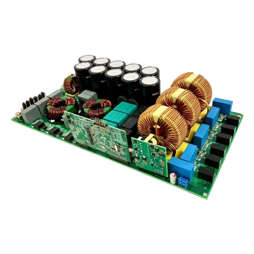
The 22kW bidirectional AFE converter reference design from Wolfspeed shows how SiC MOSFETs can be used in EV charging and energy systems. It works as a standalone AC/DC converter with both PFC (charging) and inverter (discharging) modes. The DC bus voltage is adjustable in both modes to test different conditions. The design reaches a peak efficiency of 98.5% and a power density of 4.6kW/L, and is provided as a full design package for developing SiC-based systems.
The design uses a six-switch, two-level AFE topology to enable bidirectional operation. It runs at a fixed switching frequency in both modes, which keeps control simple and makes system behavior easier to predict during testing. In PFC mode, it supports both three-phase and single-phase inputs. Three-phase operation allows full power, while single-phase operation is used at lower power levels. It handles a wide input range and regulates the DC output over a broad voltage window. The DC output voltage can be adjusted to match the needs of the next stage.
In inverter mode, the converter takes a DC input and provides a single-phase AC output suitable for on-board charger use. The DC input range and output capability allow testing of typical discharge conditions without changing the hardware setup. The switching frequency remains fixed, which helps maintain predictable operation. For three-phase inverter testing, the setup is limited to signal verification and is not intended for full power operation.
Control and monitoring are managed through a graphical user interface connected over a CAN bus. This interface is used to select power flow direction, configure the converter, and monitor operation. In rectifier mode, the output voltage can be set through the interface. In inverter mode, the output is fixed for single-phase operation.
The system supports both three-phase and single-phase inputs, making it usable across different setups. The same flexibility is maintained at the DC output, which can be adjusted based on system requirements. This allows the design to be used for validating different front-end conditions in EV and energy systems.
The design is intended for standalone use in EV on-board chargers, off-board fast charging systems, industrial charging, and energy storage applications. It does not include grid-connected inverter control, so it cannot be used for grid-tied operation. For testing, a resistive load or an electronic load must be connected at the output. In inverter mode, a resistive load is required at the AC output, while in rectifier mode either resistive or electronic load can be used at the DC side.
There are defined operating limits for safe use. Output power should remain within the rated range for both three-phase and single-phase operation, and input current must stay within limits. The hardware can support higher input voltage levels, but this is not supported by the control software. The converter should always be operated within its safe operating area as defined in the design.
Wolfspeed has tested this reference design. It comes with a bill of materials (BOM), schematics, assembly drawing, printed circuit board (PCB) layout, and more. The company’s website has additional data about the reference design. To read more about this reference design, click here.