Location based services are rapidly emerging in the modern era where users are provided with various application softwares to comply their requirements. Applications such as Google Maps, Cab Service, Food delivery service etc. have now even become the necessity for smooth survival. All these applications rely upon Global Positioning System (GPS) (Barth and Farrell 1999; Hoque 2016; Huang 2000; Kumar and Moore 2002; Wellenhoff, Lichtenegger, and Collins 1994) to physically locate the users and provide services. The system works well till the user is outside or near some landmark, but it actually fails to automatically locate the user in the indoor environments. This is due the fact that accuracy commitment of GPS relies on the efficient transmission of signals through the outer space (Golan et. al. 2011). Although, theoretically the accuracy of GPS is estimated to be 10-15 meters (Acosta and Toloza 2012), but in real time scenario, it exceeds far beyond this limit. The attenuation and reflection of signals by walls and other obstacles leads to poor localization. Thus, the satellite communication can never be employed to accurately locate user in the indoor environment. This has lead to the development of various softwares that depend upon Near Field Communication (NFC) for localization.
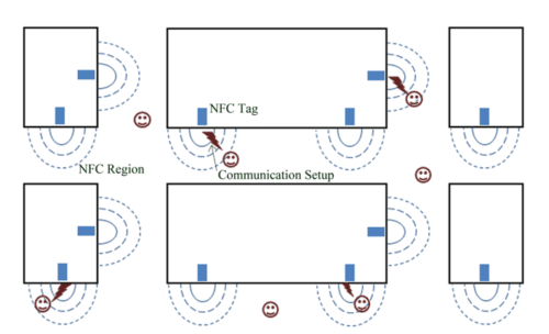
Indoor navigation, therefore, is independent of satellite communication and is implemented by physically tagging of different sections by means of some identifiers such as bar/QR codes (George and Mazel 2013; Ilkoicova, Erdelyi, and Kopacik 2014; Zhang et. al. 2015), infra-red (IR) devices (Gorostiza et. al. 2011; Raharijaona et. al. 2017), ultrasonic identifiers (Holm and Nilsen 2010; Medina, Segura, and Torre 2013), radio-frequency (RF) identifiers (Chang, Rashidzadeh, and Ahmadi 2010; Chiou, Wang, and Yeh 2010) or Bluetooth (BT) beacons (Chen et. al. 2015; Kriz, Maly, and Kozel 2016; Organero, Merino, and Kloos 2012). A hand-held device provided to the user (Android phone in our case), searches for the nearby modules and determines the current location by communicating with the tags (Figure 1). According to the current location, the application software within the hand-held device, guides the user through appropriate direction signals.
Comparison of various NFC modules
Among various modules, bar/QR coding is the simplest and economic method to tag a particular location. The hand-held device when kept near the bar/QR code, scans and decodes the information to determine the current location. Although, this method is easy to install, but the problem with this method is that the user has to locate and scan each and every code individually. The bar/QR code tagging thus, is cumbersome and time-consuming. In addition to this, it is nearly impossible for blind users to rely upon this technology. Infrared localization solves this problem as it broadcasts a unique ID corresponding to a particular node. The information broadcasted by the IR transmitters can then be read by the IR receivers that are present in the hand-held device. Although, it eliminates the problem of physical scanning of the tags but it still requires scanning in a line of sight mode (Gorostiza et. al. 2011; Raharijaona et. al. 2017). Another drawback of IR tagging is the possibility of interference of the infrared light with natural or artificial lights. Although, the problem of interference can be eliminated by replacing the IR modules with ultrasonic identifiers but the issue of line of sight still remains with this technology. The RF identifier description tags solve both the problems of interference and the line of sight by spreading the information at a larger extent. The RF identifier tags can even store and broadcast the information of the surrounding environment as well. But, the battery consumption rate of RF transmission is higher as compared to the other technologies, which constraints the application of RF tags. In addition to this, the high range of RF transmitters also results in localization errors. Although, this error can be minimised by measuring strength of the RF signal but the weather conditions and the physical condition of the transmitting and receiving antennas greatly affect the signal strength.

BT technology, on the other hand, caters all the problems, which are experienced by the above mentioned technologies. It does not require line of sight communication as the unique id (UUID) corresponding to the location is broadcasted by a BT tag in a broader way. The range of bluetooth signal is 4-5 m (Kriz, Maly, and Kozel 2016), therefore, the possibility of localization error is least in this technology. However, battery consumption still remains a major problem if we program the BT beacon to broadcast the information regarding local environment as well. Therefore, in the present work, we have devised an algorithm that relies only upon the address of the BT beacon and doesn’t require any communication setup with it. The only requirement in this protocol is that the beacon must be “ON”.
We have implemented the indoor navigation system using this protocol in our college where mapping of various sections of the college is done with the UUID of the corresponding BT beacons. Based on this, an Android application has been developed that constantly searches for a nearby BT tag for navigation. It calculates the path that routes from current location to the destination, by scanning blueprint of the college. The novelty of this algorithm lies in its versatility. It can be implemented at any area merely by supplying the blueprint of the floor plan in the form of a 2-D matrix.
Pre-requisites for the Algorithm Implementation
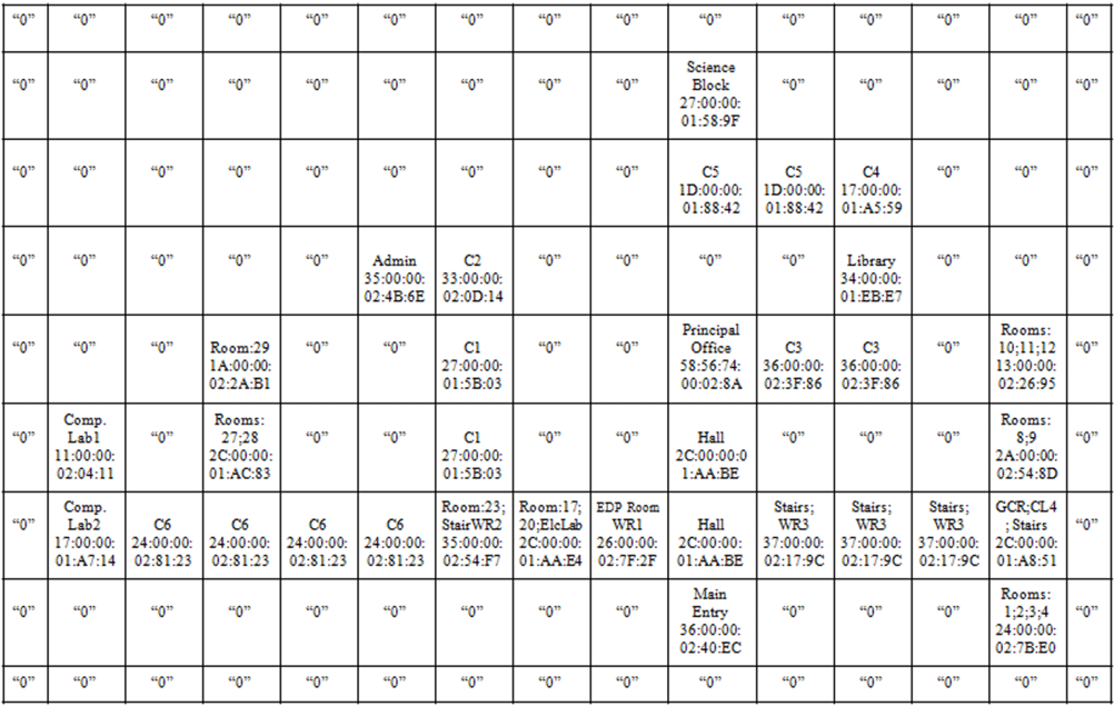
For implementation of this algorithm, we identified various locations in the college premises where BT tagging can be done for easy navigation. A map in the form of a 2D matrix has been developed that explicitly shows various sections of the college according to their physical location. The map also depicts various directional attributes required for development of a pathway between source and destination. In addition to this, the non walk able directions from a particular node are shown as ‘null’ in the map that helps algorithm while determining the pathway. Care has also been taken to insert ‘null’ rows and columns between two pathways, which are not interconnected to each other. This reduces the complexity of the so developed algorithm. Border elements of the matrix are also named as ‘null’ for the same purpose. In addition to this, a parallel 2D matrix is also defined that maps the locations of the college premises with the UUID of the corresponding BT tags.
The Algorithm
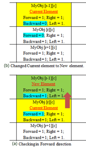
As soon as the App is launched, it reads both the above-mentioned matrices and creates an object matrix as myobj[ ][ ], that contains collective information about every place in college such as name, UUID of the corresponding BT tag and direction flags (Figure 2). The four flags namely forward, backward, left and right are initially set to “1” indicating that all the direction movements from a matrix element are allowed. Afterwards, algorithm determines the current location of the user by searching the BT devices available in its vicinity. The App reads the UUID of the available devices and checks if it is one of the BT tags stored in the matrix. As soon as the match is found, it stores the spot name corresponding to the BT device as source. At the same instance, App also asks the user about his/her destination via a drop down list.
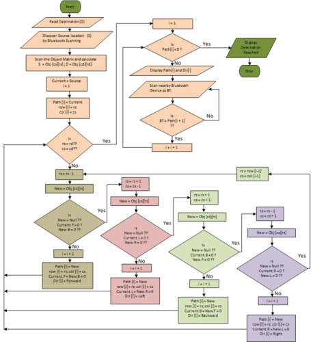
After locating source and destination cells in myobj [ ][ ] matrix, program starts building a pathway array routing towards destination. First of all, it scans a new element in the upward direction of the source element in myobj [ ][ ] matrix. If a “non-null” element is found, algorithm checks the status of the forward flag of the current element and backward flag of the new element. If both are “1” then algorithm routes the pathway through this new element (Figure 3(a)) and sets the forward flag of the current element and backward flag of new element to “0” (Figure 3(b)). This is done to ensure that these elements are traversed only once. The search then continues in a similar manner. As soon as a “null” element is found in the upward direction, the search is initiated towards Left (moving in anti-clockwise direction) and if a non “null” element is discovered then pathway is routed through this element. Subsequently, the status of Left flag of the current element and Right flag of the new element is also set to “0” for reasons as stated above. Similarly, search continues for destination element by exploring matrix in all the four directions in anti-clockwise manner i.e. Upward, Left, Downward and Right. If at a point, an element is encountered where all the four directions are restricted the pathway array is modified by removing this element and search is initiated from the previous one i.e. second last element of the pathway. The flags play an important role in determining the route towards destination as they block the algorithm from connecting the path through an element, which has already been routed. The flowchart of the so devised algorithm is shown in Figure 4.
On finding the destination, the pathway array along with a direction array is transferred to another function that instructs user in real time scenario. It keeps on checking for the presence of any new BT device and on finding a device it verifies whether the UUID of the device is among the ones stored in the matrix. After the verification, it matches if the address is the same as the one expected by the pathway array and issues direction commands using direction array. The process continues till the user reaches destination and the BT device (at destination) is discovered by the Android device.
Testing and Analysis
We have tested the so developed Android Software by placing the BT tags at different locations in the college. The commercially available Bluetooth dongles BT-163 were used for this purpose. A total of 24 BT devices were kept to map the ground floor of the college and a minimum gap of 10 meters is maintained between the nearby BT devices to avoid any localization error. Once the BT devices were plugged in DC adapters, the Android App, already installed in a smart phone, is launched. The App is observed to be quite useful in reaching different locations of the college. Care has been taken to group adjacent rooms and tagging them by a BT device so that a single device is observed at a given location. Multiple users are able to navigate in the college premises at any instance.
Conclusions
The App is universal and can be used for indoor navigation at any public area such as hospitals, shopping malls by merely supplying the blueprint of the space along with BT tagging at important spots. The database in the form of 2D matrix is the only constraint for App usage, which can be easily be modified according to the physical attributes of the space. By releasing the app on the website of the concerned public area, the user can be benefited via easy navigation.
Acknowledgements
The financial assistance from Science Centre, SGTB Khalsa College, University of Delhi (Sanction No. SGTBKC/SC/SP/2017/04/514 dated 31 May 2017) is gratefully acknowledged. Thanks are also due to Dr. P. Arun, Associate Professor, Department of Electronics, SGTB Khalsa College for his continuous support and mentorship.
References
- Acosta, N., and J. Toloza. 2012 “Techniques to Improve the GPS Precision.” International Journal of Advanced Computer Science and Applications 3(8): 125-130.
- Barth, M., and J. A. Farrell. 1999 The Global Positioning System and Inertial Navigation. New York: McGraw-Hill.
- Chang, N., R. Rashidzadeh, and M. Ahmadi. 2010 “Robust indoor positioning using differential Wi-Fi access points.” IEEE Transactions on Consumer Electronics 56(3): 1860–1867.
- Chen, Z., Q. Zhu, H. Jiang, and Y. C. Soh. 2015 “Indoor Localization using Smartphone Sensors and ibeacons.” Proceedings of IEEE 10th Conference on Industrial Electronics and Applications, New Zealand 1723-1728.
- Chiou, Y. S., C. Wang, and S. Yeh, 2010 “An Adaptive Location Estimator using Tracking Algorithms for Indoor WLANs.” Wireless Networks 16(7): 1987–2012.
- Golan, C. O., J. R. Rodriguez-Perez, J. M. Torres, and P. T. G. Nieto. 2011 “Analysis of the Influence of Forest Environments on the Accuracy of GPS Measurements by using Genetic Algorithms.” Mathematical and Computer Modelling 54(7-8): 1829-1834.
- George, L., and A. Mazel. 2013 “Humanoid Robot Indoor Navigation based on 2D Bar Codes: Application to the NAO Robot.” Proceedings of13th IEEE-RAS International Conference on Humanoid Robots 329-335.
- Gorostiza, E. M., J. L. Galilea, F. J. Meca, D. S. Monzú, F. E. Zapata, and L. P. Puerto. 2011 “Infrared Sensor System for Mobile-Robot Positioning in Intelligent Spaces.” Sensors 11: 5416-5438.
- Holm, S., and C. Nilsen. 2010 “Robust ultrasonic indoor positioning using transmitter arrays.” Proceedings of International Conference. on Indoor Positioning and Indoor Navigation, Zurich 1-5.
- Hoque, M. Z. 2016 “Basic Concept of GPS and its Applications.” IOSR Journal of Humanities and Social Sciences 21(3): 31-37.
- Huang, J. 2000 All About GPS: Sherlock Holmes Guide to the Global Positioning System. USA: Acme Service.
- Ilkovicova, L., J. Erdelyi, and A. Kopacik. 2014 “Positioning in Indoor Environment using QR Codes.” Proceedings of 6th International Conference on Engineering Surveying Prague, Czech Republic 117-122.
- Kumar, S. and K. B. Moore. 2002 “The Evolution of Global Positioning System Technology.” Journal of Science Education and Technology 11(1): 59-80.
- Kriz, P., F. Maly, and T. Kozel. 2016 “Improving Indoor Localization using Bluetooth Low Energy Beacons.” Mobile Information Systems 2083094(1-11).
- Liu, H., H. Dorasi, P. Banerjee, and J. Liu.2009 “Survey of Wireless Indoor Positioning Techniques and Systems.” IEEE Transactions on Systems; Man and Cybernetics Part C 37(6): 10670-1080.
- Medina, C., J. C. Segura, and A. D. Torre. 2013 “Ultrasound Indoor Positioning System Based on a Low-Power Wireless Sensor Network Providing Sub-Centimeter Accuracy.” Sensors 13: 3501-3526.
- Organero, M., P. J. Merino, and C. D. Kloos. 2012 “Using Bluetooth to Implement a Pervasive Indoor Positioning System with Minimal requirements at the Application Level.” Mobile Information Systems 8(1): 73-82.
- Raharijaona, T., R. Mawonou, T. V. Nguyen, F. Colonnier, M. Boyron, J. Diperi, and S. Viollet. 2017 “Local Positioning System Using Flickering Infrared LEDs.” Sensors 17(11) 2518(1-16).
- Wellenhoff, B. H., H. Lichtenegger H, and J. Collins. 1994 GPS: Theory and New York: Springer.
- Zhang, H., C. Zhang, W. Yang, and C. Chen. 2015 “Localization and Navigation using QR Code for Mobile Robot in Indoor Environment.” Proceedings of IEEE International Conference on Robotics and Biometics 2501-2506.
Author(s): By Inderpreet Singh and Tarun Thakur, Department of Electronics, SGTB Khalsa College, University of Delhi