Every now and then there is an innovation or advancement that changes the way we operate, the way the world operates. These innovations and advancements in technology create opportunities for businesses and provide improved features to consumers. These are also widely and swiftly adopted. USB Type-C is one such technology advancement that will soon be found in most devices. Apple and Google have taken the lead, whereas companies like Dell and many more are following suit.
USB interface is the most widely-adopted interface specification that is being used across all industries. This interface has slowly eliminated legacy serial and parallel ports. Now with advancements in computing technologies, devices are far more efficient and have reduced form factors. This has necessitated a change in the existing USB connectors.
USB Type-C specification is targeted towards new, compact and power-hungry devices and brings in a new flavour to the USB connector. This new ecosystem is also managed by another new specification, namely, USB Power Delivery (PD) specification, which allows managing power and functionality over the new USB Type-C connector.

This article aims to provide an insight into USB Type-C specification, USB PD specification and new functionalities you shall see and experience with the new USB Type-C ecosystem.
USB Type-C overview
USB Type-C cable and connector specifications cover mechanical, assembly and connection detection and configuration part of the USB Type-C ecosystem.

Unlike the legacy USB connector that has separate connectors for host and devices, Type-C connector uses the same connector for both host and device. The host and device relationship is negotiated using the configuration channel (CC) signal.
USB Type-C interface can be classified into two major types, namely, USB Type-C receptacle and USB Type-C plug.
USB Type-C receptacle. USB Type-C interface on a host or device is generally a receptacle connector as illustrated in Fig. 1.
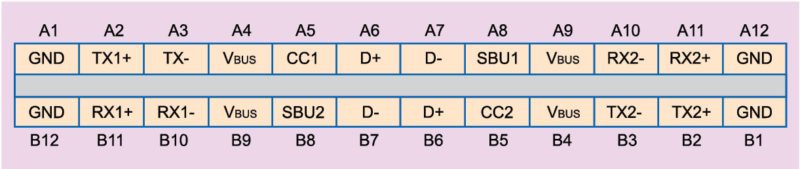
The receptacle in Fig. 1 provides multiple sets of signals to enable the desired functionality irrespective of the plug orientation. For a full-featured USB Type-C receptacle, all indicated signals are required.
USB Type-C plug. USB Type-C plug interface is a connector that is present in a cable or device like mouse or flash drive with only one CC pin and one set of USB 2.0 lines as shown in Fig. 2. The single CC pin allows orientation detection and the other CC pin of the receptacle is used for sourcing VCONN.
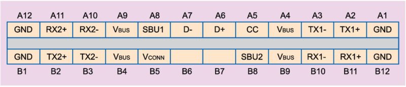
It is important to note that the super-speed lines are cross-connected on Tx and Rx in a cable.
Let us now take a brief look at the signal lines on the USB Type-C connector.
Configuration channel pins. CC1/CC2/CC. A CC signal is used to detect connection, orientation and also configure the devices into their operating modes. Based on connection orientation, one of the CC lines acts as VCONN signal to provide power to the other end.
Power pins. VBUS are for USB bus power and can carry up to 20V/5A. These are available only after connection detection.
VCONN are used to provide power to the attached plug and are applied via the unused CC pin based on connection orientation.
Auxiliary pins. SBU1/SBU2. The side-band use (SBU) pins are provided for adding additional functionality either through future USB specification or during alternate mode functionality or as an audio accessory.
USB 2.0 pins. DP/DM. D+ and D- pins are used to support USB 2.0 in all three modes, namely, low speed, full speed and high speed. These pins are provided as pairs in a receptacle to support the plug-flipping feature and are shorted in the plug connector.
Super-speed pins. RXn+/RXn-, TXn+/TXn-. These lines are used to implement Rx and Tx of USB 3.1 super-speed interface. These are shared by other interfaces when in alternate mode.
USB PD specification
Even before the new USB Type-C connector was introduced, USB-IF published USB PD specification, which defines how a USB interface can deliver 20V to its port partner. Version 1.0 of the specification uses BFSK on VBUS line for protocol communication.
Later, with the introduction of USB Type-C interface connector, USB PD specification has moved on from BFSK on VBUS to BMC based protocol communication on the CC signal line. A new specification version 2.0 has been released with the above-mentioned changes allowing USB PD protocol to negotiate higher power with the port partner and also jump to alternate functionalities like Displayport, MHL and others over USB Type-C signals.
A USB Type-C device can be broadly classified into two categories: USB Type-C device and USB Type-C device with PD capability. A standalone USB Type-C device supports up to 5V/3A operations and orientation detection, whereas a USB-Type-C device with PD capability supports up to 20V/5A operation and multiple interfaces using alternate modes.
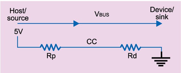
USB Type-C host or down stream facing port (DFP) to USB Type-C device or upstream facing port (UFP) connection. When two simple forms of USB Type-C devices, a USB host and a USB device, are connected, a USB host will present an Rp on the CC line and a USB device will present an Rd on the CC line as shown in Fig. 3.
When the above devices get connected, a drop in the CC line for a DFP and a rise in the CC line for a UFP confirms a connection. The rise and drop is to a predefined voltage range as defined by USB Type-C specification.
Based on the CC line voltage range, a UFP will identify the type of DFP connected and its power capabilities. Also, a DFP can identify if a UFP is connected directly or through a USB Type-C cable with VCONN requirement.
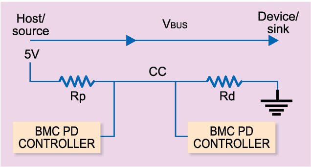
USB Type-C host (DFP) to USB Type-C device (UFP) with PD support. A USB Type-C device with PD support is an advanced USB Type-C device that provides or consumes up to 20V/5A power. It can also enter modal operations to reuse USB Type-C signals for additional functionalities. Fig. 4 illustrates USB Type-C device with PD support connection.
PD communication using PD controller starts after a successful USB Type-C connection. At the start of the process, a PD source starts sending its capabilities over the CC line using BMC encoding. The sink decodes capabilities of the source and requests the power it requires. Based on the request, the source may accept the request and change its VBUS to output the requested power. The source then sends a source-ready packet to the sink indicating acceptance.
When the port partners agree on power, state is called contract. This is the basic state requirement for any further protocol or mode negotiation.
Things you can do with USB Type-C
A USB Type-C cable plays a key role in the USB Type-C ecosystem and can dictate the behaviour of the ecosystem. In the USB Type-C environment, cable products are called electronically-marked cables that can be built with intelligence for robust and better user experience.
The flip side to this is that users need to be educated about the cables’ capability. This section explores key things that a USB Type-C cable can do, which the legacy USB cables can not.
Can talk. Unlike legacy USB cables, USB Type-C cables can be electronically marked and these respond to commands from a host device. In a USB Type-C ecosystem, a host sends series of discover commands to know about the cable and decide further action on how to set up the ecosystem. Thus, a cable plays a key role in deciding the USB Type-C ecosystem.
Can decide the power a source can provide. During the discover process, a host device receives identity of a Type-C cable that contains details like manufacturer name, type of cable, USB capabilities, VBUS current handling capability and so on. This information about VBUS current capability restricts a power provider its power capability advertisement. This means, even though a power provider is capable of providing 5A to a consumer and the cable in its identity communicates its limits as 1.5A, current capability is restricted to 1.5A.
Can be active or passive. A USB Type-C cable can be categorised as electronically-marked or non-electronically-marked cables, where the latter is dumb and does not contain any electronics inside.
Electronically-marked cables can be further classified as passive cables that are USB Type-C cables that do not support data bus signal-conditioning circuits but can respond to discover commands, and active cables that are Type-C cables that support data bus signal-conditioning circuits along with discover commands.
This classification of the cables enables bringing more interesting functionalities along with some complications to the end user.
Can enter modes. Type-C connectors allow functionalities like Thunderbolt or HDMI over existing USB signal lines. This is achieved through CC protocol. Such alternate modes are not restricted to a host or a device but can also be extended to a cable. For example, these alternate modes can help an active enable signal conditioning or at times perform some other proprietary action before entering alternate mode between a host and a device.
USB Type-C hub
Another major change the USB Type-C technology brings in is on the USB hub front, which is now a multi-function device that supports functionalities like Display Port or MHL, along with USB in a USB hub solution.
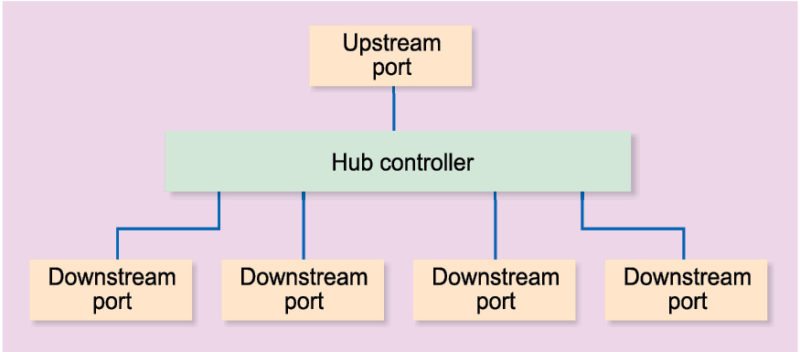
Let us now explore what a legacy hub solution looks like and how it can be modified to a Type-C solution. Fig. 5 illustrates a simple legacy hub controller with four downstream ports and an upstream port, all supporting USB functionality.
In simple terms, a USB Type-C hub solution is just a tweak of the above legacy solution with Type-C controllers managing ports and signals as illustrated in Fig. 2.
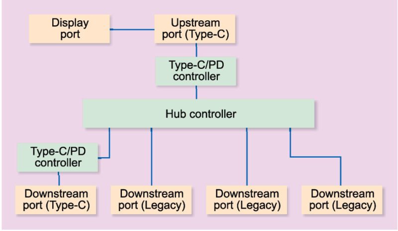
Fig. 6 is a break up of a USB Type hub, which has the following features:
• Three USB-A 3.0
• Mini display port
• Two USB-C
From Fig. 6, it is easy to understand how an existing legacy USB hub design can be tweaked to a USB Type-C hub. It is important to note that in this new hub model a USB Type-C controller manages the signal lines of the USB Type-C connector after successful CC protocol negotiation.
Some key points to remember in a USB Type-C hub solution are:
• Only an upstream port of a hub can support alternate mode, that is, functionality other than USB.
• When operating in display port mode, a USB Type-C hub may not support USB 3.0 functionality and will operate in USB 2.0 mode.
Rajaram Regupathy works with GoArks Software Systems, developing USB Type-C and USB solutions. He has product patents in embedded domain and is a senior ACM member. He has published books on Linux USB, Android USB and USB Type-C