


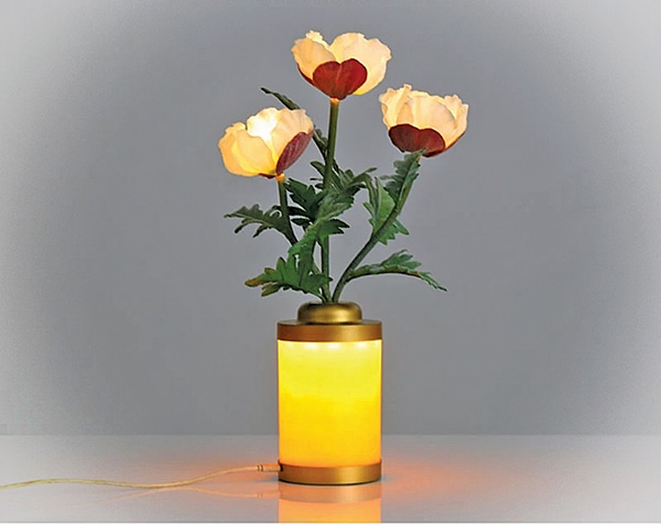
This USB LED vase is a simple yet elegant device that fuses art with electronics to create a decorative lighting display. Powered directly from a standard USB port, it uses readily available components such as MOSFETs, resistors, capacitors, and LEDs to produce a striking, dynamic sequence of lights.
POC Video Tutorial
The design operates on the principle of a ring oscillator, where LEDs illuminate sequentially in a rotating pattern. This continuous flow of light produces a calming, decorative effect, particularly when the LEDs are housed within a transparent or semi-transparent vase. Owing to its straightforward design, the device suits both beginners and hobbyists, offering a practical way to grasp the fundamentals of electronic oscillators and explore creative circuit applications.
Fig. 1 illustrates the suggested design by the author.

| Part List |
| Semiconductors: T1-T3 – 2N7000 MOSFET LED1, LED3 – 5mm yellow/amber LED2 – 5mm green Resistors (all 1/4-watt, ±5% carbon): R1-R3 – 330Ω R4-R6 – 1Ω Capacitors: C1-C3 – 2.2µF, 16V electrolytic or 47nF, ceramic disc C4 – 100nF ceramic disc Miscellaneous: USB – USB B type with a cable with a male pin |
Circuit and Working
Fig. 2 shows the circuit diagram of the fancy LED light vase. It uses three 2N7000 N-channel MOSFETs in a ring configuration, each driving one LED. Two yellow or amber and one green LED are used here. The gate of each MOSFET is connected to an RC low-pass filter, providing the necessary delay for continuous oscillation. For the 2N7000 datasheet, refer to https://diotec.com/request/datasheet/2n7000.pdf.
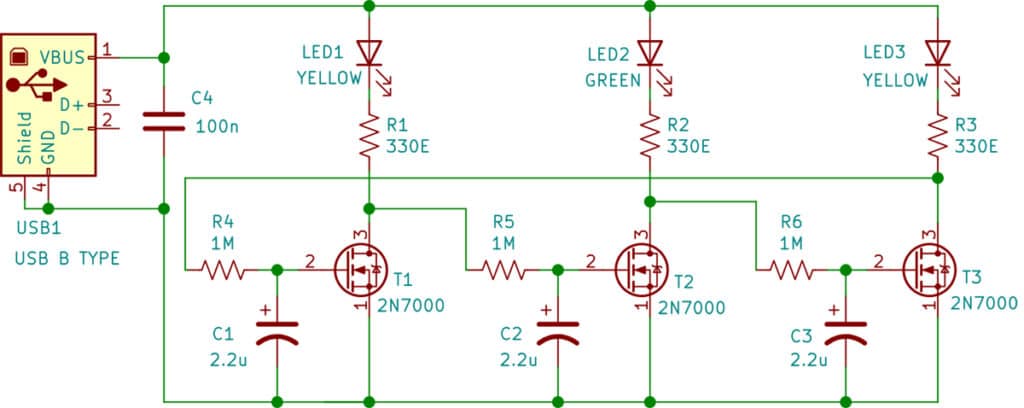
Power is supplied from a 5V USB port, making it easy to run from a laptop, charger, or power bank. Each LED has a 330Ω resistor for current limiting. Oscillation speed depends on the RC values, typically 1MΩ resistors (R4-R6) with capacitors ranging from 47nF to 2.2µF (C1-C3). A 100nF decoupling capacitor (C4) stabilises the USB supply. With 1MΩ and 47nF, the LEDs blink rapidly, producing a fast rotation. With 1MΩ and 2.2µF, they blink more slowly, creating a smoother, more pleasant sequence.
The working principle of the USB LED vase is based on a three-stage common-source ring oscillator. In this configuration, each MOSFET acts as an inverter stage, switching its respective LED on and off. The RC delay elements ensure that the signal is passed around the ring with a time lag, preventing the circuit from reaching a steady state.
Because there are an odd number of inverters (three in this case), the circuit cannot stabilise at a fixed voltage level. Instead, it continuously oscillates, producing a repeating sequence of signals. This oscillation drives the LEDs cyclically so that one LED turns on, followed by the second, then the third, and the cycle repeats endlessly. The circuit idea presented here is a three-stage common-source ring oscillator setup (https://en.wikipedia.org/wiki/Ring_oscillator).
This configuration ensures continuous oscillation, driving the LEDs in a seamless rotating sequence that gives the vase its dynamic glow.
Construction and Testing
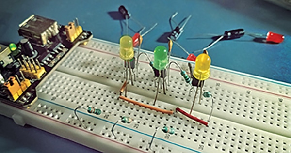
The construction of the device can be divided into several stages. To begin with, it is recommended to test the circuit on a breadboard. Connect the USB cable’s +5V and GND wires to the power rails of the breadboard, and then place the MOSFETs, resistors, capacitors, and LEDs according to the circuit diagram in Fig. 2. This allows easy troubleshooting and experimentation with different capacitor values to fine-tune the blinking speed. The author’s prototype is shown in Fig. 3.
After the breadboard prototype operates successfully, the circuit can be transferred to a perfboard or PCB. While soldering, leave sufficient spacing for the LEDs so that they can be mounted inside the vase. Thin insulated wires assist in positioning them neatly.
Choose a transparent or frosted vase for a better glow. Secure the LEDs inside using adhesive or clips, ensuring they are evenly spaced. Place the main circuit board at the bottom or in a small case to keep it safe and hidden. The circuit operates on 5V USB, consuming minimal current and generating no heat, making it safe for continuous use.
To test the device, plug it into a laptop, charger, or power bank. The LEDs should blink in sequence, creating a rotating effect. If this does not occur, check the wiring, MOSFET pin connections, and RC section values. Capacitor values can be varied to adjust the blink speed. After testing, secure the board and LEDs neatly inside the vase for the best visual effect.
Once assembled, the device serves as both a decorative lighting element and a practical demonstration of ring oscillator operation.
T.K. Hareendran is an electronics designer, hardware beta tester, technical author, and product reviewer
