


 Consider this: A criminal stops your car by force and you are left with no option but to surrender the car. The criminal drives away your car, but about 60 seconds later the engine stops running on its own and won’t restart. Unable to use the dead vehicle, the perpetrator has to abandon it. Carjacking can be prevented using the anti-carjack system described here. The circuit automatically senses carjacking and stops the vehicle. In case the circuit is accidentally tripped off, it can be easily reset using a hidden switch. Two LEDs indicate the status of the system to the vehicle driver.
Circuit description
Fig. 1 shows the circuit of the anti-carjack system. It comprises quad NAND gate CD4011 (IC1), timer NE555 (IC2), optocoupler MCT2E (IC3) and a few discrete components. The circuit is powered by 12V DC from the vehicle battery. Diode D1 protects against any possible reverse voltage. The main controlling elements of the circuit are NAND gates N1 and N2 and timer NE555.
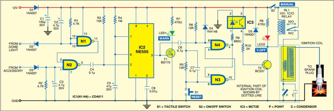
The input to gate N2 comes from a car accessory power line (such as a cigarette lighter power socket) that is energised by the ignition switch. The input to gate N1 comes from the door switch that connects the dome light. The door switches in the vehicle provide the ground return for the dome or courtesy light when any of the doors is opened.

The line connecting the door switch to the lamp is at 12V when the door is closed and at zero when any door is open. Logic signal from the dome light is fed through diode D2 to pins 12 and 13 of gate N1, which inverts it to drive pin 2 of gate N2. At the same time, the accessory power line, which is at 12V when ignition switch is turned on, connects to input pin 1 of gate N2 through diode D3.
Under normal conditions, when the ignition switch is ‘on’ and the doors closed, the output of gate N2 at pin 3 is high. However, when a door is opened, the output of gate N2 at pin 3 goes low. This negative-going output from gate N2 is coupled to the trigger input (pin 2) of NE555 (IC2), which is configured as a monostable multivibrator. Output pin 3 of IC2 goes high for a period determined by the combination of resistor R4 and capacitor C5.
The two remaining NAND gates (N3 and N4) of CD4011 are connected in a bistable multivibrator configuration with two input terminals, pins 8 and 6. The bistable configuration has two stable states with logic outputs at pin 4 and pin 10 always being opposite to each other. A negative transition at the input terminal of either gate N3 or N4 causes the bistable to change the state.
When the time period of NE555 (IC2) is over, its output pin 3 goes low. This negative-going signal is coupled to the input of gate N4 causing the bistable circuit to change the state. As a result, pin 4 of gate N4 goes high.
The high output of gate N4 forward-biases the internal LED of optocoupler MCT2E (IC3), driving the internal transistor into saturation. As a result, relay RL1 energises and its normally-closed (N/C) contact opens to cut the power to the ignition coil and stall the vehicle. When reset switch S1 is pressed, a negative transition is applied to pin 8 of gate N3. Pin 4 of gate N4 goes low to de-energise the relay and allow the vehicle to start.
The green LED (LED1) driven by MOSFET T1 glows to alert the vehicle owner if the timer has been activated, either by a carjack attempt or by inadvertent opening of a door when the ignition switch is ‘on’. LED1 gives the driver a warning that the circuit has been triggered and a lock-out will occur in about 60 seconds. The red LED (LED2) glows whenever relay RL1 energises to stall the vehicle.
The circuit is designed to be ‘fail safe.’ The N/C contact of RL1 is used to control vehicle operation. The relay doesn’t energise unless the circuit is powered and the timer triggered.
Any component failure may cause the relay to energise. To de-energise it, open jumper JP to cut off power to the relay coil circuit so that RL1 contacts remain closed.
Construction and testing
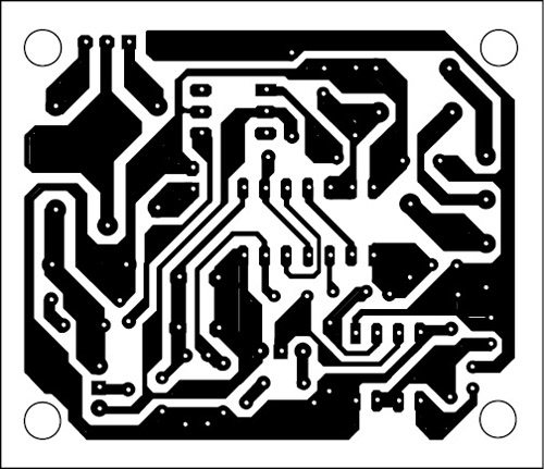
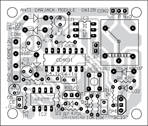
A single-side PCB for the anti-carjack system is shown in Fig. 3 and its component layout in Fig. 4. Assemble the circuit on a PCB as it minimises time and assembly errors. Carefully assemble the components and double-check for any overlooked error. Before inserting the ICs in the PCB, properly check the supply voltage at each IC’s supply terminals. Suitable connectors are provided on the PCB for connections to accessory, dome light and battery supply. Use suitable insulated wires for these connections.
Preliminary test. You need a 12V DC source, two SPST switches and a multimeter for preliminary testing of the circuit. One SPST switch (say, switch-1) is connected between the dome light and ground and the other SPST switch (say, switch-2) is connected between the accessory point and 12V.
Check the circuit for proper connection and polarity. Also, make sure that both SPST switches are open. Now turn the power ‘on.’ If LED1 glows, allow at least 60 seconds for it to go ‘off.’ If LED2 glows, press reset switch S1 to put it off.
Close test dome switch-1 by connecting to ground. Both LEDs should go off. Open test switch-1, then close test switch-2 to simulate ignition-‘on’ condition. Both LEDs should remain ‘off.’ Close both test switches (switch-1 and switch-2), then open them. LED1 should glow. It should continue to glow for about 60 seconds. When LED1 goes off, LED2 should light up. Use multimeter to verify the resistance between the N/C contact and the pole of relay RL1. It should be infinite. Now if you press reset switch S1, LED2 should go off.
If the circuit performs as described above, the system is ready to install in your vehicle.
Installation
Before installing the anti-carjack module in the vehicle, locate the wires that you will need to connect the unit (refer Fig. 2). Trace the door switch wire that turns the dome or courtesy lamp ‘on’ and any accessory wire that is powered by the battery when the ignition switch is turned on.

After locating these wires, use multimeter to verify the voltage levels at each terminals. Door switch wire should be at 12V when the door is closed and at zero volt when the door is open. The accessory wire is at 12V only when the ignition switch is turned on. The ignition coil works only when the ignition switch is ‘on.’ After verifying the proper voltage levels, disconnect the negative (chassis ground) wire from the car battery. This will ensure that any inadvertent short circuit occurring during installation will not cause any damage. Connect the module with dome light and accessory wire.
Secure the anti-carjack module at the desired location, then mount the LEDs and reset switch S1 such that the LEDs are visible to the driver, but the reset switch is hidden.
Locate the power line that goes to the ignition coil section. Cut the line as shown in the wiring diagram (Fig. 2) and connect with N/C contact and pole of relay RL1. Finally, connect ground lead of the circuit to any metal part of the car. After making all the connections, reconnect the negative (chassis ground) battery lead securely. This completes installation of the anti-carjack system.
Final test
When the installation is complete, make sure that both the LEDs are ‘off.’ If LED2 glows, press reset switch S1 to put it off. Now start the vehicle. When the engine is running, open the door and then close it. LED1 should glow. After a minute, it should go off and LED2 should glow. The vehicle engine will stall and you won’t be able to restart it. Press reset switch S1 and verify that both the LEDs are ‘off.’ Now you should be able to restart the vehicle.
Download PCB and component layout PDFs:click here
The anti-carjack module is always on-duty, fully automatic and never in need of attention. Always remember to turn off the ignition switch before leaving the vehicle. If at any time, the circuit is accidentally triggered as indicated by LED1, wait for LED2 to glow and then press reset switch S1 to put it off. The vehicle will always protect itself in the event of carjack attempt while the ignition switch is ‘on.’
Further application
You can also use this project to protect your car from theft. If at any time you wish to enable the system before leaving the vehicle, open the door before turning the ignition switch ‘off.’ LED1 will glow to indicate that the circuit has been activated. Wait a minute for LED2 to glow, which indicates that the relay is energised and the vehicle disabled. Remember, you must press reset switch S1 before starting the engine when you return.
Good evening sir, i’m doing anti carjack system as mini project but the circuit was no not working correctly. please notify me if there is any modifications on the circuit.
Thank you sir.
Please elaborate problems in detail. No modification
Please give the circuit diagram
Plz sir suggest me some major project on analog circuit without microcontroller
which electronics for you magazine did published this projct?
This project was published in Electronics For You Magazine June 2012 Issue.
how can i integrate a gps system in this circuit sir?
plz sir tell me how i attach alphanumeric keyboard to microcontroler
if u have any idea plz email me on
[email protected]
sir,please send me the video link of this project
SIR CAN I CONNECT A DC MOTOR INSTEAD OF IGNITION COIL
Please give the circuit diagram
Sir kindly send me daigram of this circuit. On this email: [email protected]
Hi Farhan, the circuit diagram is present within the article.
Sir , please send me the video link related to this project
Hi, as of now, we do not have any video related to this article.
Sir, any software code are there to implement this project?
Hi Asha, there is no software code for this particular project.
Sir, Iam doing this project. According to the operation, LED 1 should glow first then it should glow off and LED 2 glow to indicate car stall . But in my circuit both LED are glowing at a time. Could u tell me the reason why it is happening like that?
is this circuit working coz I’m planning to do this ? pls help!!!!!
Hi Shiwani, this project is verified by our EFY team. You can do it.
Sir,how this system senses the carjacking automatically.
Sir can you give details about it’s budget or price of this system and where it is available?