


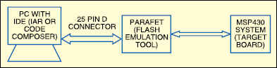
2. Hardware tool called the Flash emulation tool (FET). It connects the PC to the MSP430-based system. Two types of FET tools are available:One is based on the parallel port, while the other is based on the USB interface.
Fig.5 shows the block diagram of the MSP430 development system. The next section describes the construction of Flash Emulation Tool based on PC’s parallel port called ParaFET, which can be used to interface with any of the MSP430 target devices.
Designing MSP430 Flash emulation tool
Fig.6 shows the ParaFET circuit or Flash emulation tool based on the PC’s parallel port. As you can notice, the PC connects to this board through a 25-pin, D-type connector. The JTAG interface is established through the 14-pin FRC connector. It is important to note that the signals on the PC side are TTL-compatible and referenced to 5V, while the MSP430 works off 1.8V-3.6V supply. For Flash programming, the voltage needs to be a minimum of 2.2V.
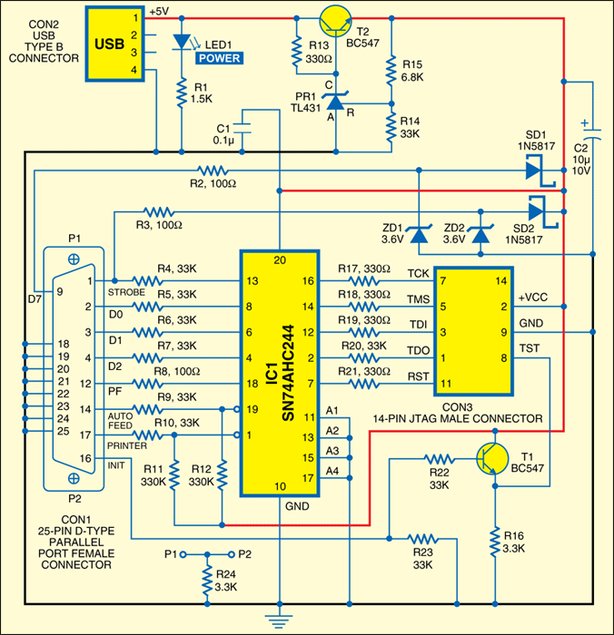
The main component that is used to interface the signals from the PC side to the MSP430 is the octal tristate buffer based on SN74AHC244 or SN-74HC244 IC. This chip along with the of the simple circuits.
Due to the current-drive limitation of the parallel port, the users have to ensure that the peripheral logic connected to the MSP430 chip doesn’t consume more than 1 mA of current. For cases where the MSP430 system consumes higher current than that supplied by the can be boosted using the PC’s USB port. The USB port has 5V supply and can drive up to 100 mA.
A USB cable needs to be connected between the FET and USB port on the PC. USB supply is taken through a precision low-dropout regulator using TL431 voltage reference, which gives a stable voltage
of 3V.
The TL431 is a three-terminal precision adjustable shunt regulator, with specified thermal stability over applicable automotive, commercial and military temperature ranges. Its output voltage can be set to any value between Vref (approximately 2.5 V) and 36V, with two external resistors. Typically, the device has output impedance of 0.2 ohm. The active output circuitry provides a very sharp turn-on characteristic, making the device an excellent replacement for Zener diode in many applications, such as on-board regulation, adjustable power supplies and switching power supplies. Presence of this voltage automatically blocks the supply from parallel-port pins 9 and 1 due to Schottky diodes SD1 and SD2.
Note that the USB connection is required here for driving extra power and regulated supply but not for any signal communication. When the peripheral logic in the target MSP430 board consumes less than 1 mA, the power from the USB port is not required. Hence, power from the USB port is used in the ParaFET when:
1. The target board consumes more than 2 mA and less than 100 mA.
2. The target board requires a well regulated 3V supply.
Construction
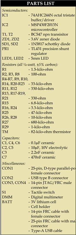
The ParaFET circuit components can be accommodated on a single-side PCB. All the components used in the circuits including the ParaFET, blinking LED and thermometer have been listed in the parts list above. An actual-size, single-side PCB layout of the ParaFET circuit is shown in Fig.7 (View as PDF) and its component layout in Fig.8 (View as PDF).
Once the components are soldered, the board can be connected to the PC’s parallel port.
The 25-pin parallel-port connector should be a female connector mounted on the PCB board. Attach the body of the female connector to the PCB board firmly. Connect it to ground line of the circuit through a 3.3-kilo-ohm resistor. P1 and P2 shown in the circuit are nothing but the connecting points of the metallic part of connector CON1 to the PCB board. A 25-pin FRC cable about 40cm in length with 25-pin parallel-port male connector at both ends can be used to connect the circuit board and the PC.
A 14-pin FRC cable about 20cm in length with 14-pin header (female) at both ends can be used to connect the target board from the JTAG connecting points. An industry-standard USB cable is required to connect the PC when extra power is required in the target board. Glowing of LED1 indicates that the board is connected to the PC.
