


Quad NAND gate 7400 (IC5) in conjunction with read and write signals from IC1 and chip-select signal from pin 14 of IC4 is used for selecting the LCD module both during read and write cycles of IC1.
PPI chip 8255 is configured with port A, port B and port C as output ports for controlling up to 24 electrical appliances via relays RL1 through RL24. Relays are energised through high-current octal Darlington arrays inside ULN2803 (IC7 through IC9) in accordance with programmed data stored in the non-volatile RAM (NV RAM) of RTC chip DS12887. There is no need of connecting external freewheeling diodes across relays as inbuilt diodes are provided in ULN2803 ICs.
All the 24 devices/electrical appliances are considered as 24 bits (three bytes at locations 200H, 201H and 202H) of the three ports (ports A, B and C) of 8255. The LCD is used for displaying real time (year, month, date, day and time in 24-hour mode) obtained from RTC DS12887 as also some other information during time setting, device programming, searching (device-switching programmed data), password entry, etc, as described later.

RTC DS12887 is clock-cum-calendar chip with 128 NV RAM (14 bytes used for its control registers and 114 bytes as general-purpose RAM). It has an inbuilt lithium battery and can retain stored data for over ten years in the absence of external power.
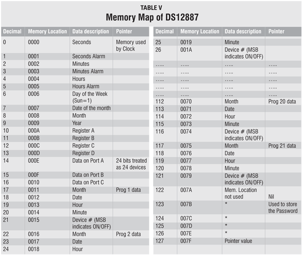
Memory map of DS12887 is shown in Table V. Data stored in location 07FH (decimal 127) indicates the address of the last RAM location used. The relay-switching data that is output from ports A, B and C of the PPI is stored as consecutive bits at 00EH, 00FH and 010H locations of the RAM. The relay/device programming timing data is stored at five consecutive locations for each device. This data includes month, date, hour and minute in first four bytes, while the fifth byte contains 5-bit address of the device with MSB indicating ‘on’/‘off ’ status of the device. Bits 6 and 7 of this byte are ‘don’t care’ bits. Address locations 123 through 126 are used for storing the 4-byte long password. Thus only 106 locations are available for storing the 5-byte long device data and as such the program for a maximum of only 21 devices out of 24 devices can be stored. The remaining three devices can be switched on/off through remote key operation as explained below.
Bit P1.1 output of IC1 is fed to transistor BC547 (T1) through R5. Transistor T1 acts like a switch for LCD backlight. So you can switch the backlight of LCD ‘on’/‘off ’ just by setting/resetting the P1.1 bit of 89C52.
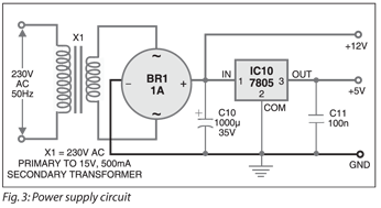 Power supply (Fig. 3). While most of the circuit requires regulated 5V for its operation, the relays and Darlington drivers IC7 through IC9 (ULN2803) are operated with unregulated 12V DC supply. A step-down transformer rated at 15V AC secondary voltage at 500 mA is used to supply 12V unregulated and 5V regulated power to the circuit. The secondary output is rectified by 1A rated bridge rectifier BR1 and smoothed by 1000μF, 35V capacitor C10. The output from the capacitor is directly fed to all the relays and ULN2803 ICs. The same output is used for regulation by 7805 (IC10). The ripple in the regulator output is filtered by capacitor C11.
An actual-size, single-side PCB for the remotely-programmable RTC interfaced microcontroller for multiple device control and power supply circuits (Figs 1 and 3) is shown in Fig. 4 (View as PDF) and its component layout in Fig. 5 (View as PDF). The connections for relays are to be extended from the 16-pin FRC connectors on the PCB. Each connector is meant for extending connections to eight relays.
Download PCB layout PDF: click here
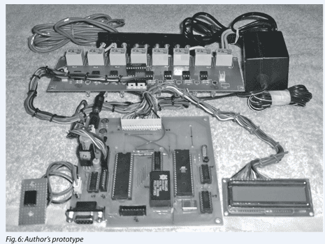
The author’s prototype is shown in Fig. 6.
Remote key operations
Refer Table IV for details of remote buttons/ keys. The functions of these keys follow:
Keys ‘0’ through ‘9’, ‘–’ and ‘sfx’. Used to switch on/off the 24 devices manually. Each time you press any of these buttons, the status of the corresponding device will toggle, i.e., its output will be the complement of the previous state.
Button ‘–’ is used as ‘10+’ button. When it is pressed, the system waits for around three seconds before the next button (which should be between ‘0’ and ‘9’ to determine the device between ‘10’ and ‘19’) is pressed. Similarly, ‘sfx’ is used as ‘20+’ key. The button following the ‘sfx’ button should be between ‘0’ and ‘3’ (as the project supports only 24 electrical appliances numbering ‘0’ through ‘23’).

May i got this assembled?
No. You have assemble the circuit by yourself
May it work, with this source code?
Please share remote control circuits for 5.1 amplifiers system