


RCL. Turns the LCD backlight ‘on’/‘off.’
PWR. Used to change the 4-digit password (initial value ‘0000’). When you press this button, the system will ask for the existing password. If the correct password is entered, it will ask for the new password. If a wrong password is entered, ‘invalid’ message will flash on the LCD.
Note that the password can be any 4-digit value, which need not be the numbers from ‘0000’ to ‘9999.’ Other buttons representing various codes are also accepted.

Timer. Used to change the real time. As the circuit operations depend on the real (set) time, changing the same is password-protected. A valid 4-digit password will let you change/ set the time. When you press ‘timer’ button, the top row on the LCD defines the format ‘Hr:Mn:ScWkDyMnYr.’ You need to enter the valid data as follows:
Hr: 00 to 23 (24-hour mode)
Mn: 00 to 59 minutes
Sc: 00 to 59 seconds
Wk: 01 to 07 (01 is Sunday)
Dy: 01 to 31 dates
Mn: 01 to 12 (01 is January)
Yr: 00 to 99 (year)
Any value out of the range will not be accepted and message ‘invalid value’ will be displayed on the LCD.
Store. Enables/disables the child lock function. You can lock the remote keypad by enabling the child lock. When you press this button, the system will prompt the message ‘Lock?’ or ‘UnLock?’ depending on the present status of the child lock. If ‘1’ is pressed, the child lock feature is enabled/disabled. Any button other than ‘1’ will be treated as zero.
PP. Takes you to programming of a task. If the NV RAM is full in DS12887, the message ‘prog memory full’ will flash on the LCD. If the memory is not full, a new device program is accepted by displaying a message in the first line of the LCD as ‘Mn Dt Hr:Mn Dv S’ and a blinking cursor will appear on the second line to take the data. ‘Mn’ indicates ‘month’ (‘01’ to ‘12’), ‘Dt’ indicates ‘date’ (‘01’ to ‘31’), ‘Hr’ indicates ‘hours’ (‘00’ to ‘23’), ‘Mn’ indicates ‘minutes’ (‘00’ to ‘59’), ‘Dv’ indicates ‘device number’ (‘00’ to ‘23’) and ‘S’ stands for ‘programmed status’ (‘1’ for ‘on’ or ‘0’ for ‘off ’). Enter the desired data in this format, which will get stored in the NV RAM of the RTC. If month (Mn) is entered
as ‘00,’ the same task will repeat every month on the same date and time. If date (Dt) is entered as ‘00,’ the same task will repeat every day on the same time.
Search. Shows the existing device programs that are stored in the memory starting from location 011H onwards one by one. Each time, you need to press CH+/CH- button to move forward/backward. In this mode, you may delete the displayed device program data entry simply by pressing ‘Mute’ button. Then the program that is residing next to this task moves to the location of the deleted task and the whole memory is refreshed.
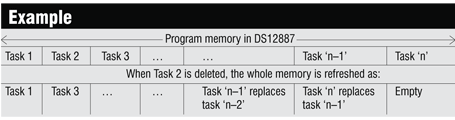
See the example shown above for clarity. The pointer value in memory location 007FH of DS12887 changes accordingly.
AC. Deletes the entire programmed data in one stroke. So use this key very cautiously.
RTC initialisation
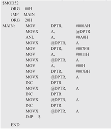 When DS12887 is shipped from the factory, the oscillator is in disabled state. The following program will make DS12887 work and also reset the password to ‘0000’ and make the program pointer to point to the location 0011H, i.e., it clears the existing tasks by making the program memory empty:
Before getting started, you need to make this program run for the first time after all the components and ICs are inserted into the circuit. That is, to make DS12887 work, burn the program shown above in microcontroller 89C52, put the programmed microcontroller in the circuit, switch on the circuit for five seconds and then turn it off. By doing so, the internal oscillator of DS12887 starts oscillating and IC DS12887 is now ready for use. Now, remove 89C52 from the circuit and load into it the main program to make the circuit work with all the features. (For more details on DS12887 RTC, refer to the datasheets.)
The monitor program in 89C52 gets the relevant time data (time, date, day, year, etc) from DS12887 RTC and displays it on the LCD. The data is also compared against the user-entered data (programmed timing data for multiple devices), which had been stored in the NV RAM of DS12887. When the timing data that was stored in the NV RAM equals the real-time data fetched from the DS12887, it sets/resets the MSB of the fifth byte of the stored program for that device. stored program for that device.
The main software program is named ‘proj.asm’. Before burning the code for main program ‘proj.asm’ into AT89C52, erase the initialisation program ‘rtcint.asm’ that is programmed initially into it.
Download source code: click here

May i got this assembled?
No. You have assemble the circuit by yourself
May it work, with this source code?
Please share remote control circuits for 5.1 amplifiers system