


 Arduino board can also be used to control electrical devices and appliances over the Internet. Just by clicking a few buttons on a webpage, the devices can be operated from a remote location. For this, the board needs to be Ethernet-enabled using Ethernet shield. This project illustrates the point by using Wiznet W5100 Ethernet shield to control a servo motor and an LED.
Circuit and working
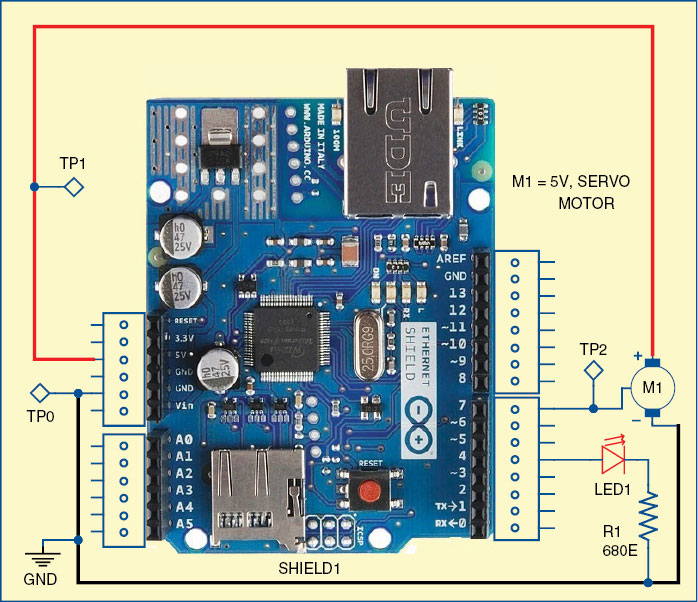
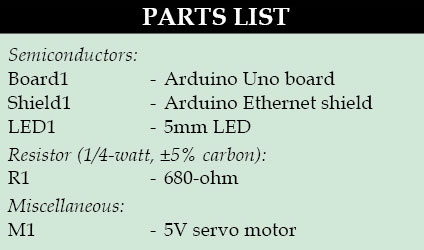
Fig. 1 shows a circuit of the web-based device controller. The circuit is built around Arduino UNO board (board1), Arduino Ethernet shield (shield1) and servo motor (M1).
Servo motor
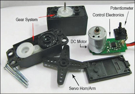
A servo motor mainly consists of a DC motor, gear system, position sensor (generally a potentiometer) and control electronics as shown in Fig. 2. The DC motor is connected to a gear mechanism, which provides feedback to a position sensor. The potentiometer allows the control circuit to monitor the current angle of the servo motor. If the shaft is at correct angle, the motor shuts off. If the circuit finds that the angle is incorrect, it will keep the motor on until the angle is correct. A normal servo is used to control the angular motion up to 180 degrees.
Angle of rotation
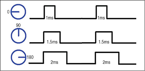
The angle of servo motor rotation is determined by the duration of a pulse that is applied to the control wire. The servo expects a pulse every 20 milliseconds (0.02 seconds). The length of the pulse will determine how far the motor rotates. A 1.5-millisecond pulse, for example, makes the motor turn to the 90-degree position (often called the neutral position). If the pulse is shorter than 1.5ms, the motor turns the shaft lesser than 90 degrees. If the pulse is longer than 1.5ms, the shaft turns closer to180 degrees as shown in Fig. 3.
 Arduino UNO board
 Arduino UNO board
Arduino is an open source electronics prototyping platform based on flexible, easy-to-use hardware and software. It is intended for artists, designers, hobbyists and anyone interested in creating interactive objects or environments.
Arduino UNO is a board based on ATmega328 microcontroller. It consists of 14 digital input/output pins, six analogue inputs, a USB connection for programming the on-board microcontroller, power jack, an ICSP header and a reset button. It is operated with a 16MHz crystal oscillator and contains everything needed to support the microcontroller. It is very easy to use as the user simply needs to connect it to a computer with a USB cable or power it with an AC-to-DC adaptor or battery to get started. The microcontroller on the board is programmed using Arduino programming language and Arduino development environment.
Arduino Ethernet shield
The Arduino Ethernet shield allows an Arduino board to connect to the Internet. It is based on the Wiznet W5100 Ethernet chip, which provides a network (IP) stack capable of both TCP and UDP. It supports up to four simultaneous socket connections. Use the Ethernet library to write sketches which connect to the Internet using the shield.
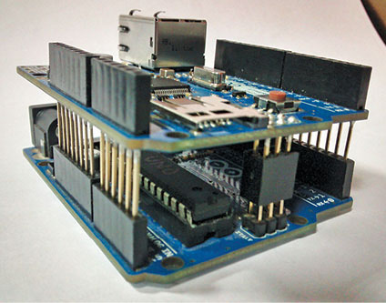
The Ethernet shield connects to an Arduino board using long-lead stackable headers (refer Fig. 4). This keeps the pin layout intact and allows another shield to be stacked on top, if needed.
The Ethernet shield has a standard RJ-45 connection, with an integrated line transformer and Power over Ethernet (PoE) enabled.
There is an onboard microSD card slot, which can be used to store files for serving over the network. It is compatible with the Arduino UNO and Arduino Mega (using the Ethernet library). The onboard microSD card reader is accessible through the SD Library. When working with this library, digital pin 4 of the Arduino cannot be used.
The shield also includes a reset controller, to ensure that the W5100 Ethernet module is properly reset on power-up. Previous revisions of the shield are not compatible with the Mega board and need to be manually reset after power-up.
Arduino communicates with both the W5100 and SD card using the SPI bus (through the ICSP header). They are connected to digital pins 10, 11, 12 and 13 on the UNO and pins 50, 51 and 52 on the Mega. On both the boards, pin 10 (slave select or SS pin) is used to select the W5100 and pin 4 for the SD card.
On the Mega, the hardware SS pin (pin 53) is not used to select either W5100 or SD card, but it must be kept as an output, otherwise SPI interface won’t work.
Note that, because the W5100 and SD card share the SPI bus, only one can be made active at a time. If you are using both peripherals in your program, this should be taken care of by the corresponding libraries. If you are not using one of the peripherals in your program, however, you will need to explicitly deselect it. To do this with the SD card, set pin 4 as an output and write a ‘high’ to it. For the W5100, set digital pin 10 as a high output.
The reset button on the shield resets both the W5100 and the Arduino board.
Digital pins 4 and 7 of the shield (Shield1) are connected to LED1 and control pin of servo motor (M1), respectively.
Software
The software for this project is written in Arduino programming language. The Arduino UNO is programmed using Arduino IDE software. ATmega328 on Arduino UNO comes with a boot loader that allows you to upload new code to it without the use of external hardware programmer. It communicates using the STK500 protocol. You can also bypass the boot loader and program the microcontroller through ICSP (in-circuit serial programming) header, but using boot loader programming is quick and easy.
Select the correct board from ‘Tools -> Board’ menu in Arduino IDE and burn the program (sketch) through standard USB port in the computer.
Construction and testing
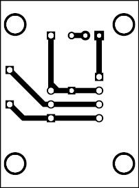
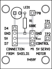
A single-side PCB for the web-based device controller using Arduino is shown in Fig. 5 and its component layout in Fig. 6. Assemble the components on the recommended PCB to minimize assembly errors. Carefully assemble the components and double-check for any overlooked error.
To check working of the project, follow the steps below:
- Connect the servo as shown in the circuit diagram (Fig. 1)
- Power up the Arduino board through power adaptor
- Connect Ethernet shield on top of the Arduino board
- Connect the Ethernet shield with LAN cable through your router
- Ping the IP address 192.168.0.160, or change the IP address as per your router setting.
You need to change the IP address in the source code, recompile and burn into the microcontroller
Now you can access the servo (M1) and LED1 using this IP address on your browser. If the connection is successful, you can see following user-interface controls on your browser:
- Turn on LED, Turn off LED
- Rotate Left, Rotate Right
You can switch on/off LED1 and also control the servo motor M1 by clicking the appropriate button.
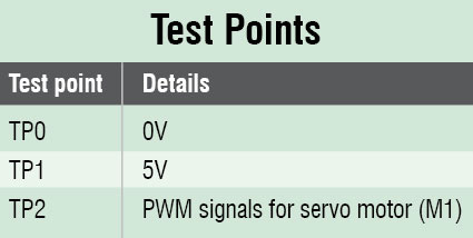
To test the circuit for proper functioning, verify the correct 5V supply for the circuit at TP1 with respect to TP0.
Download PCB and Component Layout PDFs for Web-Based Device Controller: click here
Download Source Code: click here
You can also check the DIY Arduino Projects.
The author is a final-year B.Tech (ECE) student of Ansal Institute of Technology, Gurgaon

Sir please help me.i am a computer peripherals chiplevel service technician.i wish to learn arduino Uno programming and project s. Plus give me a guide line
Bro, there are multiple courses available on coursera/Edx you can check and learn….I think it helps you
Sir I have made this project but now I want to add log in credentials to the web page.
Can you please suggest the code?
Thank you in advance…