


This human safety device offers a compact, reliable solution for detecting, monitoring, and responding to emergencies involving vulnerable individuals.
Built using an IndusBoard Coin, it addresses the urgent need for immediate assistance, particularly for the elderly, children, and those with medical conditions.
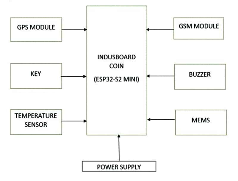
The device integrates a MEMS sensor for fall detection, a temperature sensor for health monitoring, and GPS and GSM modules for location tracking and communication. Automatic and manual response capabilities enhance its effectiveness.

POC Video Tutorial
Also Check: IoT-based Fall Detection Device
The MEMS sensor identifies falls or sudden movements, sending alerts with GPS coordinates and sensor data to emergency contacts via SMS.
Also Check: Smallest GPS Tracker
The temperature sensor triggers alerts for abnormal readings, potentially indicating a health crisis. An emergency button allows manual alert activation, ensuring user control in critical situations.
| Bill of Materials | |
| Components | Quantity |
| IndusBoard Coin | 1 |
| SIM800L GSM module | 1 |
| L86 GPS module | 1 |
| Buzzer | 1 |
| Switch (optional) | 1 |
| 3.3V or 3.7V battery | 1 |
The GSM module ensures alerts are delivered via SMS even in areas without internet connectivity, making it suitable for remote and outdoor locations. Despite dependencies on GSM network coverage and battery life, the device represents a significant advancement in personal safety.
Future iterations could incorporate additional sensors, wearable designs, and a mobile app for real-time tracking and control.

Harnessing advanced sensor and communication technologies, this device delivers a vital layer of security. Fig. 1 shows the prototype, Fig. 2 illustrates the block diagram, and the required components are detailed in the Bill of Materials table.
Circuit Diagram
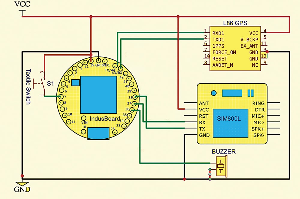
Fig. 3 shows the circuit diagram of the human safety device. It is built around the IndusBoard Coin, L86 GPS, SIM800L, a 3V battery, a tactile switch, and a buzzer.
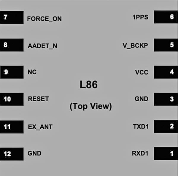
Fig. 4 illustrates the pinouts for the IndusBoard, while Fig. 5 shows the pinouts for the L86 GPS module, which operates on the same serial USART as the GSM module.
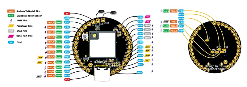
The IndusBoard Coin is a compact IoT development board designed for innovative electronics devices, measuring only 3cm. It integrates temperature, magnetic compass, and acceleration sensors within the same 3cm size, along with over 10 capacitive touch sensors.
Only the SIM800L and GPS modules need to be connected externally. The emergency button’s built-in touch sensor can serve as a switch, but a physical switch is included in this design to prevent unintentional triggers. However, this physical switch can be replaced with the inbuilt touch sensor in the code.
The GSM and GPS modules can connect to any IndusBoard pin. All pins are flexible and can be configured in the code.
Programming and Code
The library for the sensor used here is compatible with the IndusBoard, which has an inbuilt LSM303 sensor for accelerometer, magnetometer, and temperature data. To utilise this, install the STM LSM303 library.
The Adafruit GPS library is used for GPS functionality. After installing these libraries, download the code from electronicsforu.com and upload it to the device.
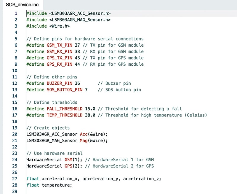
The code defines the pins and variables for the GPS, GSM, buzzer, and other components first. The acceleration, temperature, and GPS data are checked and updated within the loop.
If the acceleration threshold is exceeded, the device sends an SOS message containing the location and activates the buzzer for alerts. The system also checks for a push button press, sending an alert if triggered.
The phone number can be customised by editing the code. Fig. 6 shows the snippet of source code.
Testing
Once the code is uploaded and the device is assembled, it can be powered using the 3.3V or 3.7V battery. Pressing the SOS button sends a message to the phone number containing the location and activates the buzzer sound for an alert. The same response occurs when the acceleration threshold detects a signal, indicating a sudden fall or accident. SOS messages with location data are displayed on the right-hand side of the prototype (see Fig. 2).
Functions of the Human Safety Device
Emergency Activation: The device activates emergency protocols when the user presses the push button. The buzzer sounds to alert those nearby to an emergency situation. The GPS module retrieves the current location coordinates (latitude and longitude). The GSM module sends an SMS containing the GPS coordinates and any relevant sensor data (temperature readings) to pre-stored emergency contacts.
Automatic Alerts: The device automatically sends alerts without user intervention if the MEMS sensor detects a fall or the temperature exceeds predefined thresholds. It sends multiple SMS notifications to ensure that contacts receive the alert. It activates the buzzer for audible notifications.
Continuous Monitoring: The device remains in monitoring mode until it is turned off or reset by the user. It periodically checks for falls or temperature changes while awaiting further input. This integrated approach ensures that individuals can quickly alert their contacts in emergencies while providing critical location and health information for timely assistance.
Real-time Tracking: If integrated with periodic updates, the system can continue sending location updates to contacts, providing real-time tracking of the user’s movements.
Reset: Once the alert has been sent and the situation is handled, the system resets for subsequent use. The push button can be pressed again to initiate another alert if needed.
Outputs of Each Function
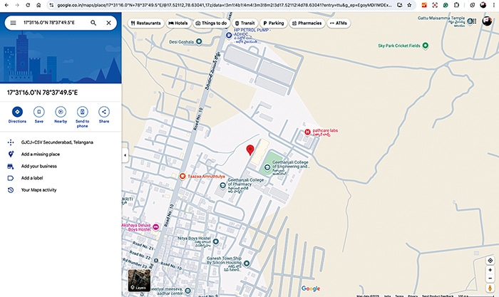
Location data – GPS coordinates: The system captures and outputs the device’s current GPS coordinates (latitude and longitude), for example, Latitude: 17.52115 and Longitude: 78.63043
Status Update:
Key button press acknowledgement. The system outputs a confirmation message indicating that the key button has been pressed, for example: ‘ALERT, EMERGENCY AT LOCATION.’
High-temperature acknowledgement. The system outputs a confirmation message indicating a high-temperature alert, for example, ‘ALERT, HIGH TEMPERATURE AT LOCATION.’
Fall acknowledgement. The system outputs a confirmation message indicating a fall alert.
For example: ‘ALERT, FALL AT LOCATION.’
Communication output through SMS notification: The system sends an SMS message to a predefined phone number with the GPS coordinates and additional information, for example: ‘ALERT, FALL AT LOCATION: https://www.google.co.in/maps/place/17.52115,78.63043.’
Alert message – Alert indication: The system logs an alert message for a central monitoring system or designated contacts, for example: ‘ALERT, FALL AT LOCATION: https://www.google.co.in/maps/place/17.52115,78.63043.’
Future Scope
The future of human safety devices holds significant promise for development and enhancement that can further improve personal safety and expand its applications.
Integration of additional health monitoring features: Incorporating heart rate sensors and blood oxygen level monitors could provide a comprehensive health profile, enabling caregivers to respond to a broader range of medical emergencies. This enhancement would benefit elderly users or those with chronic health conditions, allowing for continuous monitoring and timely interventions.
Companion mobile application: A mobile application working with the device could enable real-time monitoring, allowing family members or caregivers to track the user’s location and health metrics remotely. The app could facilitate communication between users and emergency contacts, providing a platform for sharing alerts and updates during emergencies.
Such advancements would enhance user experience and foster a greater sense of security for caregivers and families.
Raghavendra Reddy Jakkidi is pursuing a B.Tech in Electronics and Communication Engineering at Geethanjali College of Engineering and Technology, Hyderabad. He developed this project under the guidance of Dr P. Sudhakar (an Associate Professor at the same college).
