


 This simple and easy-to-use IC 555 timer tester not only tests the IC 555 timer in all its basic configurations but also tests the functionality of each pin of the timer. Once a timer is declared fit by this gadget, it will function satisfactorily in whatever mode or configuration you may try it.
The two basic configurations in which a timer IC 555 can be used are the astable and the monostable modes of operation.
IC 555 Timer Tester
When the DPDT switch (S2) is in position 1-1, the timer under test automatically gets wired as a monostable multivibrator. In this case, the monoshot can be triggered by the microswitch (S1). The debouncing circuit constituted by the two NAND gates of IC1 (N1 and N2) produces a clean rectangular pulse when the microswitch is pressed. Resistor R3, capacitor C1 and diode D1 ensure that the trigger terminal of timer IC 555 (pin 2 is the trigger terminal) gets the desired positive-to-ground trigger pulse. This differentiator circuit also ensures that the width of the trigger pulse is less than the expected monoshot output pulse.

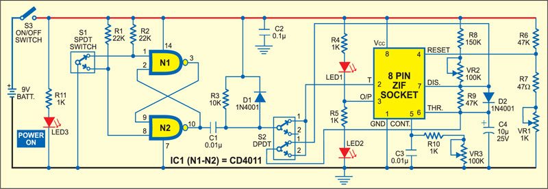
The monoshot output pulse width is a function of the series combination of resistor R8 and potentiometer VR2, and capacitor C4. When DPDT switch S2 is in position 2-2, the timer gets configured for the astable mode of operation. The output is a pulse train with the high time period determined by the series combination of resistors R8, potentiometer VR2, resistor R9 and capacitor C4, whereas the low time period is determined by resistor R9 and capacitor C4.
Circuit construction
The reset terminal of timer IC (pin 4) should be tied to Vcc normally. More precisely, the voltage at pin 4 should be greater than 0.8V. A voltage less than that resets the output. Whether you have connected the timer in the monoshot or astable mode of operation, the output goes low the moment you bring the reset terminal below 0.8V.

The control terminal (pin 5) can be used to change the high time (‘on’ time) of the output pulse train in the astable mode and the output pulse width in the monoshot mode by applying an external voltage. This external voltage basically changes the reference voltage levels of the comparators inside the IC. The levels are set by three identical resistors of usually 5 kilo-ohms inside the IC connected from Vcc to ground, at 2/3Vcc for pin 5 and 1/3Vcc for pin 2. These levels can be changed by connecting an external resistor between pin 5 and ground. Resistor R10 and potentiometer VR3 have been connected for this purpose.
Circuit calculations
The pulse width in the monoshot mode is given by:
1.1×total charging resistance×charging capacitance
This expression is valid when there is no external resistor connected at pin 5. The pulse width can be reduced by connecting an external resistor.
The high and low time periods in the astable mode are:
High time period = 0.69×chargingresistance×charging capacitance
Low time period = 0.69×dischargeresistance×capacitance
Again the expressions are true with no external resistor at pin 5. The high time period can be made to decrease by connecting an external resistor between pin 5 and ground.
Applications
The circuit can thus be used to check:
1. The timer IC in astable configuration.
2. The timer IC in monostable configuration.
3. The capability of the reset terminal to override all functions and rest the output to low.
4. The function of the control terminal to change the ‘on’ or the ‘high’ time of the output waveform in astable mode of operation and the output pulse width in monostable mode of operation.
The circuit operates off a 9V battery, which makes the gadget portable. You can construct it easily on any general-purpose PCB along with the 8-pin socket.
Test procedure
- Insert it into the socket.
- Set switch S2 in position 1-1.
- Switch on the power supply by flipping switch S3 to ‘on’ position. Power-indicator LED (LED3) glows to indicate that the circuit is ready to test the IC timer.
- If the IC is okay, LED1 glows because the IC is wired as a monoshot and in the absence of any trigger, its output is low.
- Apply the trigger pulse by momentarily pressing switch S1. LED1 stops glowing and, in turn, LED2 glows. This confirms that the output of the monoshot has gone high. After the predetermined time period, LED2 goes off and LED1 again glows. Vary preset VR2 and trigger the monoshot again through switch S1. You will find that LED2 glows this time for a longer or a smaller time period depending upon whether you increased or decreased VR2 resistance.
- For checking the reset function of the timer, trigger the monoshot again, and before the expected time is over, quickly decrease the potmeter VR1 resistance so as to bring the voltage at pin 4 below 0.8V. You will observe the output going low (indicated by glowing LED1 and extinguished LED2).
- For checking the control function of the timer IC, set potmeter VR1 again in the maximum resistance position. Also set preset VR3 in the minimum resistance position. Trigger the monoshot using switch S1. You’ll observe its output going high for a time period that is much less than that determined from the series combination of R8 and VR2, and capacitor C4. In fact, for any fixed setting of this series combination, the output pulse width can be observed to vary for different values of potmeter VR3 resistance—by triggering the monoshot several times, once for each setting of VR3.
- Now set the DPDT switch in position 2-2. LED1 and LED2 glow alternatively with the timing determined by the resistances in the charge and discharge paths. This means the timer IC is okay and wired in astable mode.
- The functions of reset and control pins can be checked in astable configuration too in the same way as discussed above for the monoshot configuration.
The article was first published in July 2005 and has recently been updated.
