


Reference design for a smart plug that can measure single-phase power and enable wireless control of equipment.
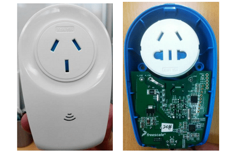
In today’s connected world, most things can be controlled wirelessly, and the credit goes to the Internet of Things (IoT). But upgrading all the appliances for wireless connectivity is neither feasible nor possible. But if you still want to control your devices remotely and monitor the power usage, you can use a smart plug to achieve wireless control and monitoring capabilities. A smart plug is a device that can be inserted into a traditional electrical outlet, enabling you to control the power supply to connected devices remotely. It adds smart functionality to regular appliances or electronics that are typically not designed to be “smart” or connected to the internet. Through the app, you can turn the connected devices on or off, set schedules for automatic operation, monitor energy usage, and sometimes even monitor or adjust the device settings remotely.
To simplify the task of designing a smart plug, NXP has released a reference design for the control and monitoring of power usage by a device. The smart plug reference design is intended for the measurement of energies in single-phase, electronic power monitors, and wireless control. The reference design is based on the MKM34Z64 microcontroller. The smart plug reference design can be extended to various areas, including lighting monitor, machine room power distribution, etc. The design implements measurement of grid voltage, current, frequency, active and reactive energies and with the WIFI chip, it uses UART and predefined command protocol to implement status display and function setting from the mobile application to the socket. This reference design can be adjusted for different loads by changing the values of relay and width of power PCB.

Features of NXP Smart Plug:
- ARM® Cortex® -M0+ core, part number MKM14Z64CHH5, 44 LGA (5 mm × 5 mm) Packaging, 50 MHz system clock, 64 KB Flash, 16 KB SRAM
- 220 V input voltage, 10 A maximum current allowed
- Current sampling uses 25 ppm 5mΩ current sampler, 24-bit SD ADC
- Voltage sampling uses 25 ppm resistive voltage network, 24 bit SD ADC
- Grid frequency detected by on chip voltage
- Single 32.768 K Crystal Input for 5 ppm RTC
- Extensible external 64 Mb SPI Flash
- 3 channel light pulse for calibration
- UART to extend WIFI module
- Socket on/off status display and setting up
- Display of current active and reactive power, apparent power, and power consumption history
- Display of historic running time
- Time and timer setting up
The system uses UART as an interface to communicate with the Wi-Fi module and also provides the required power, interrupt, and control signal. The communication module of this reference design uses the Qualcomm QCA4002 and the K22F MCU, with AllJoyn, but the reference design can be tweaked and the designer can select their own communication module as per their design requirements. The reference design also offers grid frequency detection which is detected by the analog comparator in KM. The two inputs of the comparator are connected to L and the output signal of the AC divided voltage. Apart form grid frequency detection the reference design also offers current sampling, voltage sampling and is capable of allowing currents up to 10A.

This reference design has been tested by NXP. It comes with a design guide, schematic layout, etc. You can find additional data about the reference design on the company’s website. To read more about this reference design click here.

RTC uses Seiko +/-20 ppm 32.768 kHz crystal.