


 Most commercial torchlights use three AA or AAA cells connected in series, which produces 4.5V to drive white LEDs using a current-limiting resistor. These flashlights do not drive the LEDs efficiently due to lack of a current-control circuit. Presented here is a LED Torchlight circuit that drives high, bright white LEDs from a single dry cell.
Circuit and working
ZXSC380 is a highly-integrated, surface-mount device (SMD), single- or multi-cell LED driver for applications where step-up voltage conversion from a very low input voltage is required. It requires only an external inductor to generate constant current pulses that are ideal for driving single or multiple LEDs over a wide range of operating voltages. It provides simple-to-use, low-cost, space-saving and easy-to-layout solutions.
The LED torchlight circuit consists of two modes: normal and bootstrap.

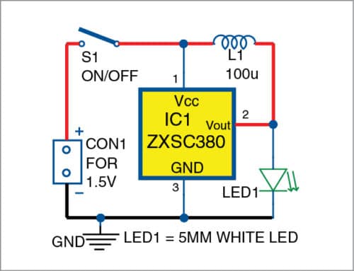
Normal mode
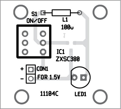
The circuit diagram of the LED Torchlight Circuit in normal mode is shown in Fig. 1. In this mode, the circuit requires only one 100µH inductor (L1) to drive LED1. Switch S1 is used to turn on/off IC1. When S1 is closed, IC1 and L1 perform step-up operation and LED1 glows.
Bootstrap mode
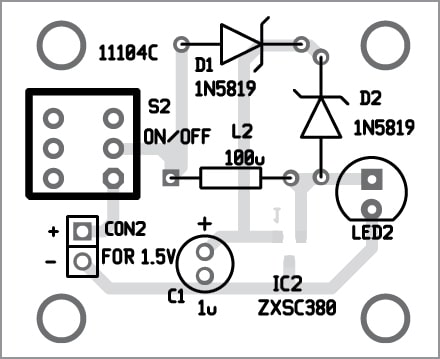
The circuit diagram of the LED Torchlight Circuit in bootstrap mode is shown in Fig. 2. In this mode, the circuit requires two additional Schottky barrier diodes (D1 and D2) and capacitor C1. When switch S2 is closed, IC2 is powered through diode D1. Inductor L2 charges till the internal switching transistor of IC2 is turned on.
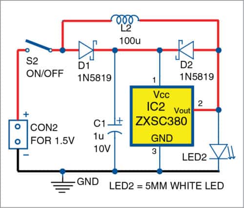
After the internal transistor is turned off, voltage across L2 reverses its polarity and voltage is given back to VCC (pin1) of IC2 through diode D2. Hence, under 1V is required to drive LED2 after startup.
In bootstrap mode, IC2 can be operated down to 0.7V typical after initial successful startup. Operation down to 0.7V typical allows further cell energy to be extracted beyond the typically quoted end of battery voltage of approximately 0.9V. This prolongs battery use time. Without bootstrap, typical startup voltage is 0.9V.
Construction and testing
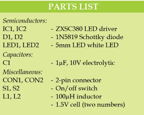
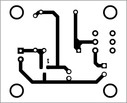
A single-side PCB layout of the torchlight in normal mode is shown in Fig. 3 and its components layout in Fig. 4. Assemble the circuit on the PCB. Since ZXSC380 is an SMD, place and solder it on the solder side of the PCB. Connect 1.5V cell across CON1.
Similarly, an actual-size PCB layout for the torchlight in bootstrap mode is shown in Fig. 5 and its components layout in Fig. 6. Assemble the circuit on the PCB. Place and solder ZXSC380 on the solder side of the PCB. Connect 1.5V across CON2.
Download PCB and component layout PDFs: click here
A. Samiuddhin is B.Tech in electrical and electronics engineering. His interests include LED lighting, power electronics, microcontrollers and Arduino programming.
Why are you using Schottky diode in this circuit.pls explain the use of Schottky diode?
Thank you for taking interest to my article. The purpose of the Schottky diode is to extract more energy from the cell. Initially, when the switch S2 is closed, the IC2 is powered from the cell through the diode D1 till the internal switching transistor is turned on(i.e., ON time). After the internal transistor turns off(i.e., OFF time), the inductor reverses its polarity and the diode D2 is forward biased. Now, the IC2 is powered by the energy from the inductor through D2 till the OFF time. This cycle continues repeatedly. This helps to extract more energy from the cell. Normally, the IC2 operated upto 0.9V from the successful startup. By using two Schottky diodes, the IC2 operated down upto 0.7V. This helps to use further energy from the cell due to the additional usage of 0.2V. For more information, read the datasheet https://www.diodes.com/assets/Datasheets/ZXSC380.pdf.