


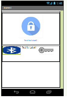
 In this project, we are going to make an OTP-based smart wireless locking system as you can see in (Fig. 1). This smart lock can generate a new password every time you unlock it, which further enhances your security level.
This DIY device is much safer than the traditional key-based system and electronic wireless lock system. If you are still using the key-based system, you are likely to land in a big problem if your key gets lost or stolen. The electronic wireless lock system is not safe either. You might forget the password and there is also a high risk of being hacked.
For your safety and security, we bring to you a DIY smart lock that has the capability to remove all these security threats and problems.

Components Required
- Arduino UNO
- Bluetooth Hc05
- LED
- Some Wires/Jumper Wires
- Servo Motor
- 5V Battery/Power Bank
- USB Type B for Programming Arduino
Bill of Materials

As we have all the components now, we can start our project.
Smart Wireless Locking System – Coding
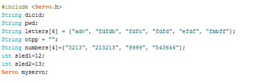
First, we need to include the library and declare the variables needed, as in a snippet of code. We include a servo library, then create a string array to generate a password. After this, we need to create a few more string variables to store password, OTP, and LED pin numbers as in snippet Fig.1 of the code.
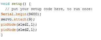
In the second part of coding, we need to set up serial and Braud rates for Bluetooth. Here I have used the 9600 Braud rate but if it didn’t work, you can use the default Braud rate of Hc 05 i.e. (38400). Then, we have to set up a pin for the servo using servo.attach (PWM pin number). After that, we can define pin mode as output for led refer (Fig.2)
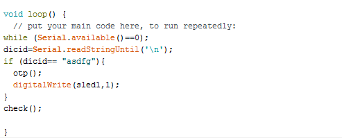
In the third part of the code, we will create a loop and check the data coming from Bluetooth. Then we create an if() statement to check the device id. If it matches, then it calls otp() function for the generation of OTP(refer to Fig. 3)
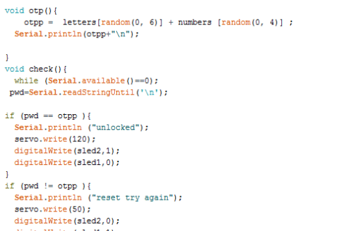
Then we need to create a check() function to check whether OTP is correct or not. If it is correct then it turns the servo to an open position (refer to Fig. 4).
Congrats! We have completed the coding part.
Now, let’s make Android APP for our project. We can make an App with two different platforms, either Android Studio or MIT app inventor. For this project, let’s choose the MIT app inventor because it’s easy to make an App with blocks without coding. Comment below if you want me to build App with Android Studio.
Recommended: Check more such interesting Arduino Projects.
APP Building
First, we need to create a layout as in the pic (Fig. 5). Just drag and drop or download the .aia file for it from the link below.
Now let’s get into the code Blocks tab, for coding.
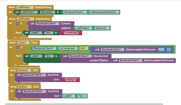
First, we need to initialize the Bluetooth list available for connection. Then we have to set the button function to send the device id according to our Arduino Code as in the pic below (Fig. 6).
Now, export the app .apk and install it on your Android phone.
You can get .apk, .aia file, and code from the link below.
Download Source codes
We are almost done now, we have completed our coding and app building. Let’s set up the components and begin connections.
Connecting Components:
| Arduino Pins | Components and Pin |
| Arduino Pin 9(pwm) | Servo Yellow Wire (signal input wire) |
| Rx | Bluetooth Module TX |
| Tx | Bluetooth Module RX |
| GND | GND Bluetooth |
| VCC | Bluetooth VCC |
| Pin 12 | LED |
| GND | Battery(-VE) |
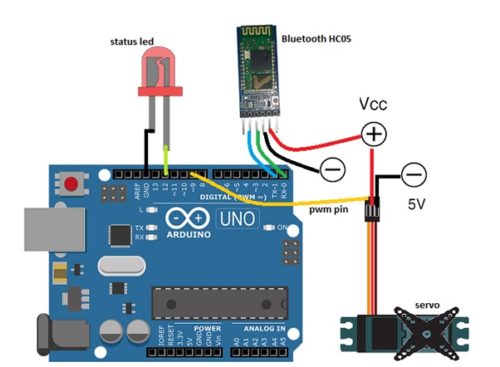
The whole circuit and connections are illustrated in the pic below (Fig. 7).
We have connected all the components now. You might not like to fry a costly Arduino board with the wrong connection. So, always crosscheck your setup to ensure that all connections are ok.
Hurray! We have now completed our awesome project on an OTP-based lock system. Just plug it in and follow the steps in the video for testing
Testing
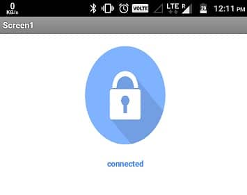
First, connect the Arduino and components to a power supply. Here I have used 5V Power Bank for it. Next, open the installed App, then turn on the Bluetooth of the phone. When you tap on the Bluetooth icon, you will get the list of Bluetooth connections for pairing. Now, tap on HC 05. On successful pairing, you will get a ‘connected’ message on the App as in Fig 8.
After that, tap on the key icon to send the device id to match. If the device id is matched, it will send an OTP to your app that you can see in the App text bar between Bluetooth and the lock icon.
Now, you can tap on the lock icon to unlock your Smart Lock. If everything is ok then the servo moves the unlocking mechanism and the onboard LED of Arduino lights up indicating successful unlock. I have used servo because of its high torque, and also because we can control the angle of its movement which helps in the unlocking mechanism of the lock.

How to connect the arduino and servo , Bluetooth to power from power bank
Cut one end of USB cable of power bank and get its +ve and -ve wire then solder that +ve wire with +ve of Bluetooth,Servo,and Arduino and -Ve wire with GND of Components.Be careful while connecting the components wrong connection may be dangerous.
in which type of complier we can run the code
Arduino IDE
Is it a matlab code or which type of coding is it
Where is the code for this project and the apk file for it
You can downlode the code and .apk file by clicking on “Downlode code” written in red color. Whole project is in zip file when you click on that, the zip file automatically get downloaded in you PC. You will also get .aia file, you can import that file in MIT App inventor and make changes in app like changing the Device ID, and layout.
How to operate the app
Turn on the Bluetooth of your phone
Open app, Tap at the Bluetooth icon
Tap at HC05 for connection,(wait few sec for connection).
Tap on the key icon to send Unique Device Id ,
when you got OTP from Arduino it will display in text box next to key Icon.
Now tap on Lock Icon on Top to Unlock.
After generation of OTP between the bluetooth icon and key icon what should I do to unlock the lock and how we know that the lock is unlocked??
Tap on lock icon the servo motor you have connected will move showing that the lock is unlocked
Hi,
Please share with me your contact details.
Thanks
Link of project code is all ready given, For any more questions you can ask in comment
Hi, how does it generate a one time password?
when ever you press key Icon the Arduino pick any random combination of numbers and letters and send that to your phone.
Where is OTP is used in this project?Means OTP send to our phone but what further?you didn’t used that OTP anywhere ,you just click on that key icon.So is the use of that otp,can u plz explain.
Hi, I get same code (asdfg) everytime I press key icon or lock icon, and the motor moves clockwise and anticlockwise and stop when either lock or key icon is pressed, how do I troubleshoot this?
Have you used the same code given in link? if yes then try to reset board and reconnect the Bluetooth to fix it.If still not solve reply with full problem you are facing,Servo motor only move when you tap on lock icon, and also wait few second when you press key icon to get the OTP. When you press key icon servo motor moves back to original position to lock and wait for new OTP.
The code is the same, it does the same thing even when I reset, in my arduino IDE there is only COM4 serial port and the LED does not light up
Check your Bluetooth and its baud rate if the Bluetooth baud rate is not correct then it send the garbage value.if still not solved then reply with whole details of you problem and tell me the steps where you are confused.
share the apk file of the code.
Hi, do you have a circuit diagram for this project using ATMEGA328P and some components excluding the arduino board?
I have made this with Arduino uno and tested it on that Right now I don’t the circuit diagram for ATMEGA328P IC . Why don’t you try it with Arduino uno or Arduino pro mini, I think Arduino pro mini best fit if you are trying to reducing the size of circuit.Still u need some help ask me
I powered the bluetooth module according to the circuit but it did not work. So we used the arduino to power the module and the module worked but the code won’t get uploaded on the board now. What changes should be made in code for this?
Also to provide the motor and the BT module 5V, we used 7805 regulator and a 9V battery.
You can’t upload the code to Arduino when the RX and TX of Bluetooth is Connected to Arduino. First unplug the Bluetooth Power and the try to upload the code.When code get successfully uploaded to Arduino ,you can connect all the components as described.
This project is nice but app portion has not been elaborated by the author. App portion creates doubt in the mind of the people who are new to Android.
This project is nice but app portion has not been elaborated by the author which creates confusion in the minds of the people who are not well conversant with android.
I have described how to use app in a previous comment please refer that,
If still confused then ask me
how to make the app…can u plz explain me in detail
First download MIT app inventor.then import .aia file that I have attached in code you will get the whole code Blocks there. if still have problem in understanding please ask me.
Hey pls can anyone tell how to create an app?
If you are a newbie then you can use MIT APP inventor,
If you are expert then you can use Android studio,
The process of app building with mit is described in the Article.
The app is not working properly .
bluetooth got connected and the otp also came but the unlock key is not .
i have checked thrice same problem is happening again and again.
plz help me ASAP.
The app is not working properly .bluetooth got connected and otp also came but the unlocking is not happening .
i need a solution of this ASAP
Tap again the key icon to unlock. If still face problem the share the whole details of error message.
By tapping the key icon ,the servo motor is not moving .
if servo motor will not move then how can it be unlocked.
when you tap key icon you get otp in text bar then you tap on big lock icon to unlock
I tried but that big lock key is not working.I even tried to tap it but its not working .
i need a solution of it.
I have re-tested the whole project and it is working fine. Please check the following points:-
1.Check your servo is it working using the sweep example
2. check the Bluetooth connection are you getting OTP after tapping on key icon
sir can you share your contact number . please sir i am facing huge problems in this project…
what problem are you facing can you elaborate in details. If you have powered the servo with external battery and powered the Arduino with different battery then make a GND common between Servo and Arduino simply attach wire between GND of Servo to GND of Arduino. Be careful during powering.
Please share the whole earrr in details what problem you are facing.
You can also try another Lock based project Biometric Lock link.
thank you sir for ur nice help .I have checked the circuit and i got fault there.
BTW thnnk you
What if the phone gets dead? Is there any other way to resolve this issue?
yes, either you can add some extra reset function to it or you can upload the app to any Google drive so that you can download the app from any other phone to unlock. You can improve it and modify it to make it more reliable. You can also share your project story with us. We love to see what you have made?
how this project is connected with internet of things(Iot)
i did’t get can you explain how it is connected to iot
Can you help me for solving my startup difficulties related this project?
Kindly elaborate your query.
do you have a documented project report on this
do you have a documented report on this project
sir can u tell me that i want to add keypad and LCD with this project then what will be the code please suggest me or give me sir
I want fingerprint sensor based unlock system,
Check this link.
Can you briefly explain working of the project?
Sir how to rotate the servo motor with continue rotation in this project please tell me sir
h0w to make the servo motor open and close have written the Arduino code & block coding correctly
cross-checked several yimes
To make the lock close and open you can use the servo shaft and move it to a different angle and position. For example, for locj=king you might need to move the servo shaft to 120 angle you can do this bu adding servo.write(120) in code.
Where is OTP is used in this project?Means OTP send to our phone but what further?you didn’t used that OTP anywhere ,you just click on that key icon.So what is the use of that otp,can u plz explain.
Hi Ashwini sir, just wanted your help on buying ready hardware for the door lock software we planning to develop our own can you suggest some good vendors
Thanks
can i get the documentation of this project
What documentation do you need can you elaborate. You mean you need pdf of the project
For online simulation, Which software would be use?
Proteus
how can we generate new password everytime can you please explain in detail
Tap on key icon in-app to generate otp
sir in proteus how this will work
sir can you explian how otp is used in this project.
we are not getting OTP generated, consequently servomotor is not working. HELP
please help ASAP
Connect bluetooth to HC05 –>tap on the key icon and a OTP can be seen in text bex below
If still face problem explain me in detail can contact me on whats app 7061350809
please check your whatsapp
OTP is not generating, Please help
ASAP
I can’t get the codes and apk file from “download codes” option. It is showing error . Plz provide a link for the codes and apk and aia files so that i can make this project .
Mam after clicking download option it is showing error then how I can download app, code files
Kindly temporary turn off Antivirus and then redownload.
How many bluetooth HC 05 do we need here?
I am getting that Error 516:Unable to write:Broken pipe how to solve it. Kindly Please help me with this.
Probably the app is made years ago and the new latest version of android SDK changed please recreate the app with kodular with the latest version of SDK using .aia file or code blocks example. Or you can use any Bluetooth terminal app from the play store to send the OTP and receive OTP .I still face problem the contact me on 7061350809
How do we get device id?
can u suggest name of app?
can u provide documentation(PDF) of this project
i am not getting the app ….can u pls make a video how to create this app using mit app invertor?
What’s app me your query on 7061350809
I Need Program Only
how we can generate otp
how we can generate otp in this project
install the .apk file in android phone . You will get it fin code zip folder. Then pair Bluetooth and connect in app you have just installed and now tap on key icon
APk file is in zip folder attached with article . Click on download code extract zip file
Where is OTP is used in this project? Means OTP send to our phone but what further? You didn’t used that OTP anywhere ,you just click on that key icon. So what is the use of that OTP, can u plz explain.
zEvery time you want to unlock you need new password to unlock the one time password received by app is top that you need to send back to lock. The apk is made to make it simpler so app itself receive the OTP and do all stuff instead of you . Ypu can use the Bluetooth terminal app to send the device id to get otp from lock and retype the otp to lock to open it.
zEvery time you want to unlock you need new password to unlock the one time password received by app is top that you need to send back to lock. The apk is made to make it simpler so app itself receive the OTP and do all stuff instead of you . Ypu can use the Bluetooth terminal app to send the device id to get otp from lock and retype the otp to lock to open it.
i make all connections and put same code but the app is not working.when i press key button nothing is happening what i have to do