


 Linear actuators are widely used in robotics and mechatronics. But getting their accurate position is complicated. Linear Actuators are very costly (prices start from 10K) and can go up to several centimeters only also Position Controlled Linear Actuator is hard to find.
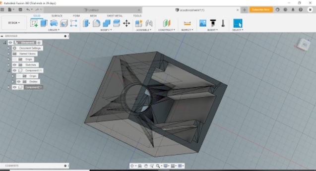
So, I have designed a position controlled linear actuator on my own by conceptualising the mechanism, body, code and electronic circuit. On combining all of them, the final product will be ready.

Mechanism Design
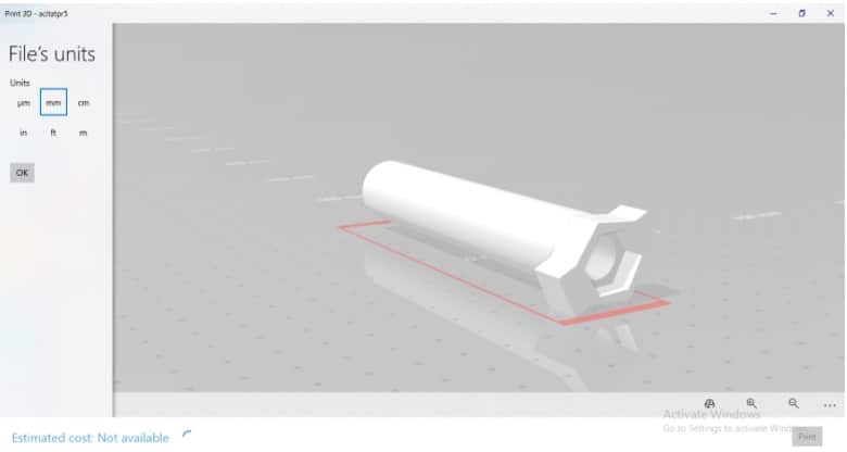
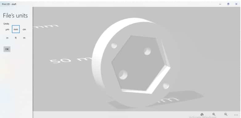
First, design the shaft and the actuator piston/rod for position controlled linear actuator. As the required mechanical parts have already been created (using Fusion 360) for you, there is no need to design them again. If you wish, you can choose any other CAD software like DesignSpark or Tinkercad.
For the actuator, 15cm lead screws with 2mm pitch are to be used. Measure the width and height of the lead screws and their nuts. Then design the parts according to the measurements.

If you are an electronics/mechatronics/electromechanical engineering student or wish to learn component designing, then you can go through the .stl and .f3d design files attached with the article. Else you can skip them and directly get the 3D printed parts with the same lead screw and nut measurements and other parts in the bill of materials.
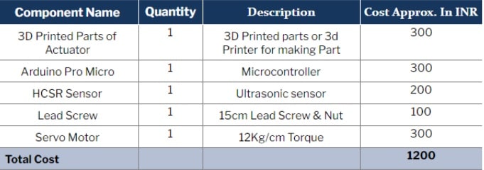
Bill of Materials
Mechanism Assembly
After getting all the 3D printed parts and other electronics, now let’s assemble the actuator.First, put the lead screw head in the small-sized, 3D printed shaft connector (Refer Fig 5). Second, put the bolt on the 3D printed moving part of the actuator having a length of 15cm (Refer Fig 6). Third, place the lead screw inside the actuator part by rotating clockwise. Make sure that it is firmly fixed inside.Next, put the actuator’s moving part to a 3D printed main body part (Refer Fig 7).

Finally, attach the servo motor to the shaft of the linear actuator with glue and screw. Then fix the servo on the main body of the actuator using a screw and glue.
Coding
Begin by installing the ultrasonic sensor library. To do so, open the Library Manager located in Tools. Search the library name and install it.
For the code, create a variable that will store the value for the current position.
After that, define the pin for the sensor and create a setup function to set the serial communication baud rate with Arduino. This will enable it to get the current position of the actuator and subsequently send a command to move the actuator to the desired position.
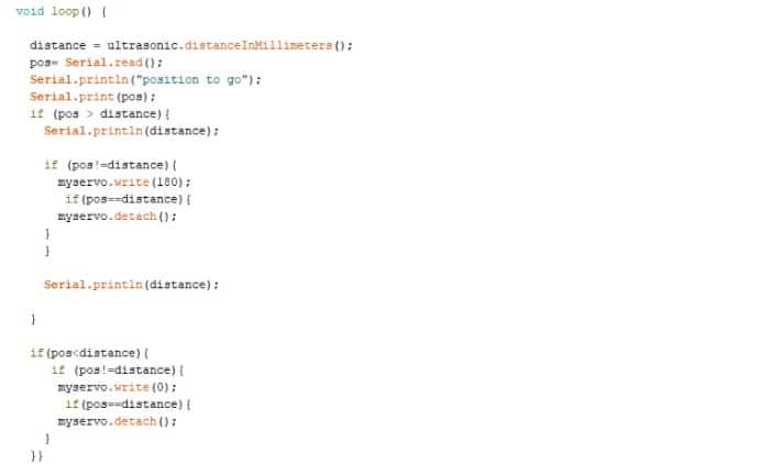
Next, create a loop through which the current actuator position (in mm) can be obtained regularly from the sensor. Also add an if() condition to check the values of current versus desired positions. If the desired position value is greater than the current position value, then the servo should move clockwise until the actuator reaches the desired position. And if the value is less, then the servo should move anticlockwise until the current position of the actuator matches the desired position.

Connection
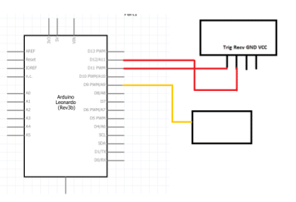
Make the following connections:
- Servo to a 5-9V battery
- Signal pin (yellow) to pin 9 of Arduino
- Sensor TRIG to pin 11 of Arduino
- REC pin to 12 of Arduino
Power the sensor using the VCC pin of Arduino. Connect the GND pin on Arduino with the GND pin of the sensor.
Testing
After connecting both the battery and servo, now connect the Arduino to a PC. Open the Serial Monitor and enter the distance value (in mm) that the actuator has to move.

