Here is a simple and low-cost circuit of pull-pin security alarm. While travelling, rig the alarm unit to your luggage using a home-made security cable. When somebody tries to cut or remove the security cable loop to steal the luggage, the internal circuitry immediately detects and sounds an audio alarm.

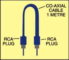
Fig. 1 shows the pull-pin security alarm circuit. The control part is built around MOSFET T1, relay RL1 and a few discrete components. The alarm sound generator is built around transistors T2 and T3, speaker LS1 and a few discrete components. The circuit is powered by a compact 12V battery. If possible, try using a 12V, 2.8Ah rechargeable battery pack (see Fig. 2). The security cable is shown in Fig. 3.
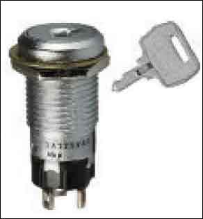
Working of the circuit is very simple. The ends of the security cable are linked to the circuit through RCA sockets J1 and J2. When key-lock type power switch S1 (shown in Fig. 4) is turned to ‘on’ position, 12V supply from the battery is provided to the circuit. As J1 and J2 are shorted by the security loop, MOSFET T1 (BS170) is cut off and relay RL1 de-energises. During this sleep mode, LED1 lights up and there is no alarm sound. This means your luggage is safe.


To test whether the alarm is working or not, simply press switch S2 momentarily. If the speaker sounds, the alarm is functioning perfectly and is ready to use.
In the absence of a security loop, J1 and J2 don’t short. MOSFET T1 (BS170) conducts to energise relay RL1. The ground supply is routed to the alarm sound generator via normally-opened (N/O) contacts of the relay. During this changeover time, the relay becomes latched and the alarm sounds until it is reset by power switch S1. During this alarm mode, LED2 lights up. R1 and ZD1 ensure proper conduction of MOSFET T1.
The alarm sound generator provides loud acoustic power output to an 8-ohm, 1W loudspeaker with a 12V supply. Transistors T2 and T3 form a complementary amplifier pair with positive (regenerative) feedback provided to the base of T2 via R6 and C3. The circuit oscillates on a frequency set by the C3-R6 combination and the base bias voltage of T2. The base bias of T2 is determined by potential-divider resistors R4 and R3. You can experiment with different R-C values to get the output tone of your choice.

Assemble the circuit on a general-purpose PCB. After testing it for proper working, house it in a convenient, tamper-proof metal box of proper size. The proposed alarm unit (including LEDs and switches) is shown in Fig. 5. Fig. 6 shows the security alarm rigged to a briefcase using the security cable.
EFY note. The alarm generator part can be replaced with any 12V-powered transistor/IC alarm circuit without much difficulty.