


 Every organisation needs an attendance system to obtain data about its working hours and also keep track of its employee’s punch in and out times. With state-of-the-art technology, this is becoming even more advanced, such as biometric attendance or RFID card-based attendance (Smart attendance system).

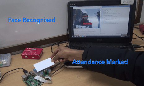
So, today we will make a smart attendance system that can reliably check the punch in and punch out times. It follows two steps to confirm attendance:
- It checks the face of the person.
- Then it checks the RFID tag to mark attendance.
What can it do?
- It can automatically record the entry and exit times (through a gate/door) using low cost RFID tags.
- It has a face recognition feature for noting the entry and exit. This ensures accuracy and hence, no cheating takes place.
- It can automatically save data and keep a record of entry and exit with the help of a facial picture.
Where can it be used?
- Offices (for attendance).
- Hotels (to automatically record check in and check out times with the help of face recognition for safety).
- Airports (for automatic check in and check out with the help smart RFID airline ticket).
- Hall, multiplexes, banks, auditoriums (for managing entry and exit of the crowd).
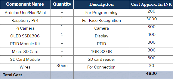
Before starting our project, let’s collect the following components:
Bill of materials
NOTE FOR READER:-
- Here in this project, you can either use 1 Arduino or 2 Arduino. if you are using 1 Arduino then the SPI and I2C components connect to the Arduino SPI and I2C pins as in the circuit diagram. You can combine both circuits and code.
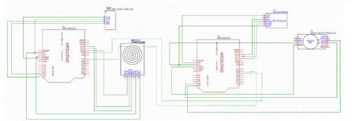
- If the circuit looks complex then you can use 2 Arduino and 2 codes attached with the article will the article need to upload in Arduino one by one and the component need to connect according to the following circuit diagram
- Here in article 2 Arduino based system is described to make it easy to look
- The Arduino got connected to raspberry pi and both connect via serial Arduino 1 mySerial(6, 5); // RX, TX to Arduino 2 pins mySerial(9, 7). Arduino that has SD connected to raspberry pi USB.
Prerequisite
Before starting our code, we need to setup some libraries in our Arduino IDE
To do so, go to Tools → Manage Libraries → Library Manager and install the following libraries:
- Ug82 Oled library
- MFRC522
Then search and install the libraries
After that, setup the following libraries for Python:
- Serial
- Dlib
- Cv2
- Face recognition
To install the above libraries in Python, follow the instructions given in the libraries’ official page
Or you can use the following command to install the library:
sudo pip install library name
Coding
Now after doing all the basic setup, we can start our coding.
Here, we create three codes for three different functions
- The SD card writing code
- The RFID reading code
- The face recognition code
The SD card writing code
This part of the code reads the name sent by the Raspberry Pi and the RFID and then saves the attendance data (date and time) in the SD card.
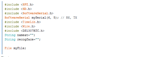
First of all, we will initialise the libraries like Time, SD, SPI, Wire. These will be followed by the variables, which will store different values. (Refer Fig 1.)
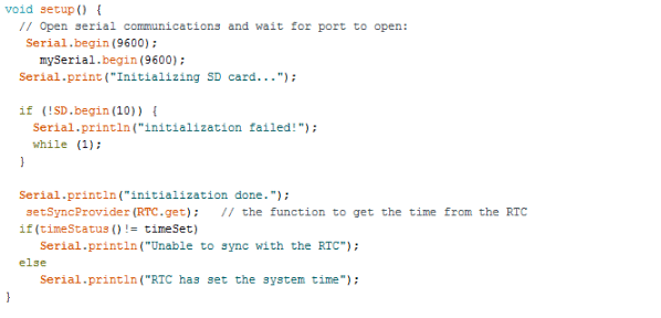
Now, we create a setup function to setup the baud rate for serial communication, SPI and I2C. (Refer Fig 2.)
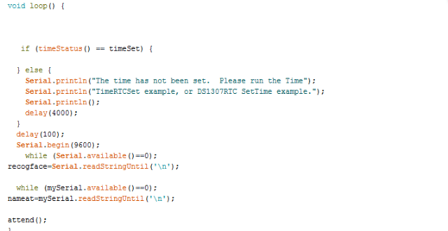
Next, we will create a loop function that will check the name stored in the RFID device and the face that was recognised by the Raspberry Pi. This will call the function named ‘attend’ to save the data in the SD card. (Refer Fig 3.)
Now, we will create a function called ‘attend’ that will save the attendance data to the SD card. (Refer Fig 4)
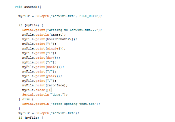
Now our SD card code is finished.
The RFID reading code
In this code, we will include the libraries like MFRC522, SPI and Software Serial along with the pin nos. for Software Serial (Refer Fig 5.)
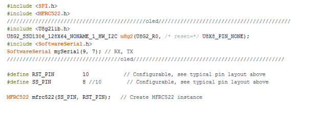
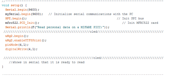
After that, we setup the RFID card and Software Serial baud rate in the setup function. (Refer Fig 6.)
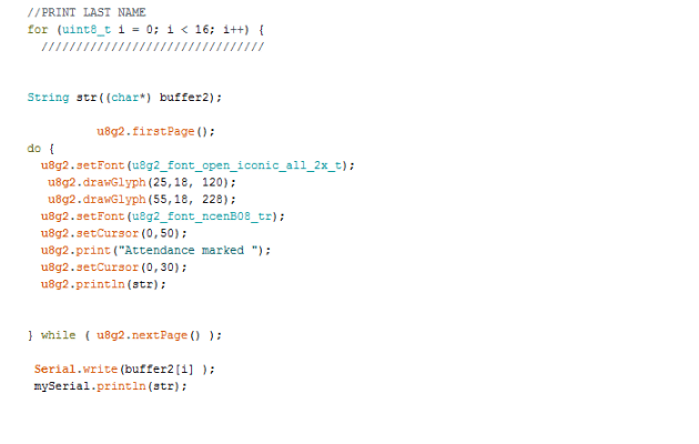
Then we create a loop function that will check the RFID for a person’s name and will later send it from the RFID cards/tags to another Arduino to mark the attendance (Refer Fig 7.)
Now, we will create a face recognition code for Raspberry that will recognise the face and send it to the Arduino.
Face recognition Code
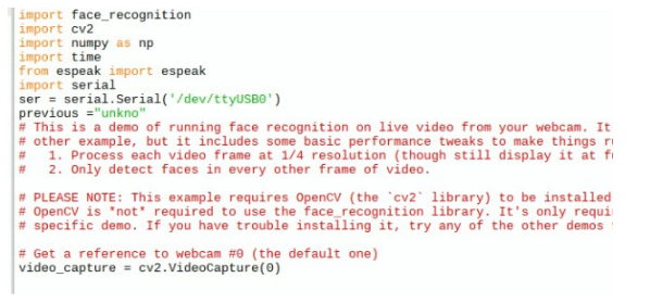
Here, we will create a face recognition code for marking attendance. First, we need to import the required libraries like serial, cv2, espeak (optional), face_recognition, numpy in our code. (Refer Fig 8.)
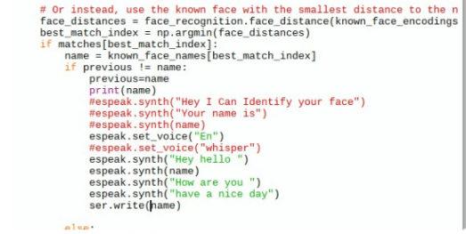
Then after setting the image a file and name we try to detect the person face in code and then after detection of name we send the name over serial port as in Code snippet below.
Now we have completed our coding so we can connect the components
Connection
Arduino 1 to RFID module connection
| Arduino 1 | RFID |
| 3.3V pin of Arduino. | VCC |
| pin 9. | RST |
| GND | GND |
| pin 12. | MSO |
| pin 11. | MOSI |
| pin 10. | SCK |
Arduino 2 to SD card module connection
| Arduino 2 | Sd Card Module |
| 5V | VCC |
| GND | GND |
| Pin 13 | SCK |
| PIn 11 | MOSI |
| pin 12. | MISO |
Arduino 1 to OLED module connection
| Arduino 1 | OLED |
| 5V | VCC |
| GND | GND |
| SCK | SCK |
| SDA | SDA |
Arduino 2 to RTC module connection
| Arduino 2 | RTC |
| 5V | VCC |
| GND | GND |
| SCK | SCK |
| SDA | SDA |
For Software Serial connection of the Arduino boards, connect the Software Serial Rx of Arduino 1 to Tx of Software Serial of Arduino 2 and vice versa.
Now connect the data cable of Arduino 2 to USB of Raspberry Pi.
Then connect the camera of Raspberry Pi to the camera port of Raspberry Pi.
Testing
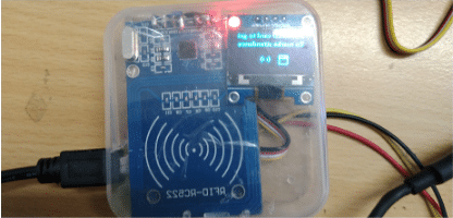
Now, power both the Arduinos and Raspberry Pi to run the face script of Python. Then bring your face in front of the camera and after its recognition, put the RFID card on the RFID module. After a successful reading of the card, the name and attendance confirmation will be shown in the OLED display. At the same time, the 2nd Arduino will save the attendance time along with the RFID name and the person’s face. To see the whole database of smart attendance system, open the text file of attendance in the SD card.
Note: To set the name of the RFID card, run the Read-Write code of RFID module and give the name. The Read – Write code can be found in the example of MFRC522 library.

Hello. Currently I am doing this project as my hobby because it is interesting. I got two questions:
1. Why is the display not turning on even I follow every connection?
2. For the SD card writing code, how to apply it? Does it need to copy to sd card or upload to arduino? Or something?
First, you need to upload the written code to Arduino and then write data on RFID card then upload the attendance code.
For OLED check the OLED address by I2c scanner you can find that code in wire library of arduino
While running attendance_sd_card_final1, it stucks at RTC has set the system time. What to do next?
Can you elaborate? You can ser the Rtc time using the RTC example code
And do we need 2 arduino for this projecT?
Yes
Yes
A most interesting project.
However what I do not understand really is why go to all this trouble when you can actually buy a fully commercial device that does all of this for the same price or less ( $60 USD ) off Alibaba ?
I am doing this project. This project is a helpful one for applying to our real life. Can you provide any flow chart & tell about the libraries in detail
I want to do this project. Can you please elaborate what is the work of Python here? & why am I not getting the libraries from manage libraries of Arduino
I am doing this project. Can you please tell me where to install the libraries of python? Should I upload the source codes after the full hardware connection?
You can upload the code first and then make a connection, Because if the previous code in the Arduino use any digital i/o
You can upload the code first and then make a connection, Because if the previous code in the Arduino use any digital i/o
Where can I find the face recognition code
Hi Sakif, the Source Code is present at the end of the article.
I know, but where should I install these libraries:
Serial
Dlib
Cv2
Face recognition?
To Raspberry pi board
Sorry for bothering again & again. I was asking in which software? & when we upload the code to arduino shall we upload the both codes in both arduinos??? And shall anything else be connected to the arduinos?
Can I get your Email or whatsapp to contact you. It would be very helpful
You can contact me at [email protected]
I meant in which software. Arduino IDE??? or somewhere else??? One more advice please, in Windows operating system, how can I first capture the images for image processing. You guys used something of linux
At the time how many person can scan their face and scan their tag id
By doing this project how many can go through this??
How many inputs????