


 This circuit produces a rotating-wheel like LED lights pattern, which can be used to decorate public halls during parties, festivals, and marriage functions. The concept is based on the persistence of vision.
Circuit and working
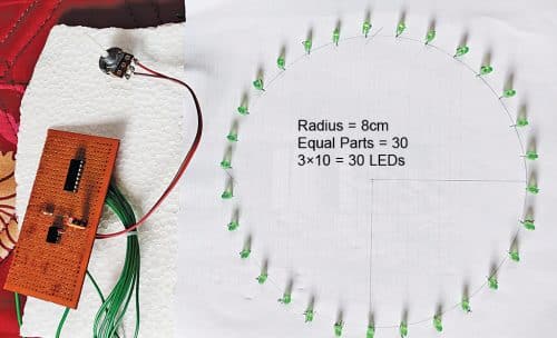
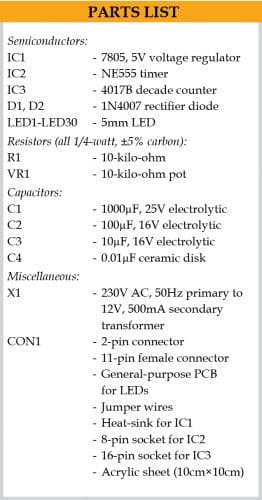
The author’s prototype is shown in Fig. 1 and the circuit diagram in Fig. 2. It is built around 12V-0-12V, 500mA step-down centre-tapped transformer (X1), two 1N4007 rectifier diodes (D1 and D2), 5V voltage regulator 7805 (IC1), NE555 timer (IC2), decade counter 4017B (IC3), and thirty 5mm LEDs (LED1 through LED30).
Regulated power supply for the circuit is derived from full-wave rectifier built using diodes (D1 and D2), transformer X1, 5V regulator 7805 (IC1), and two capacitors (C1 and C2). The regulated 5V output of IC1 is used to drive the timer and counter circuits.

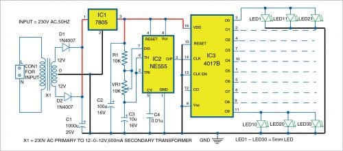
The 4017B (IC3) decade counter has ten outputs (Q0 through Q9). Each output goes high on receiving a clock input at its pin 14. Ten clock inputs are required to make all the ten outputs high. Each output remains high for a full clock cycle.
NE555 timer (IC2), configured as Astable multivibrator, is used as clock source for decade counter IC3. The clock pulse generated is available at output pin 3 of IC2. The frequency of the clock pulse can be calculated using the relationship:

F=1/(0.69(R1+2xVR1)C3)
In this project, three LEDs are connected to each output pin of IC3. Thus, a total of thirty LEDs are connected across the ten output pins of IC3.
Construction and testing
The LEDs are placed, equally spaced, in a circle of about 8cm radius on a board and fixed as shown in Fig. 1.
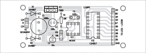
A PCB layout for the rotating LED lights circuit is shown in Fig. 3 and its components layout in Fig. 4. After assembling the circuit on the PCB, connect the secondary side of transformer X1.
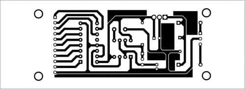
Download PCB and component layout PDFs: click here
The LEDs can be mounted on a suitable-size Veroboard, or an acrylic sheet, or any other stiff board. Draw a circle of about 8cm radius on the board and mount the LEDs with equal spacing between them and with proper LED sequence as shown in Fig. 5.
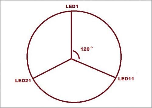
If you are using a Veroboard, you can easily solder each LED on the board and extend the connections to the PCB using flexible wires. For acrylic sheet, you will have to make hole for each LED and fix it using glue gun or with any other adhesive material. Solder all LED pins to flexible wires and extend them to the PCB connector marked as ‘To LED1-LED30’ in Fig. 4.
When the circuit is switched on, each set of three LED string connected to the outputs of IC3 glows one by one, sequentially, making the whole setup look like a rotating wheel due to persistence of vision.
Pamarthi Kanakaraja is an assistant professor (R&D cell) at K.L. University, Vaddeswaram, Guntur district, Andhra Pradesh

How to connect to power supply? Details are missing.
After assembling the circuit on the PCB, connect the secondary side of transformer X1 to X1 Secondary marked in the PCB. It is mentioned in the article above. The transformer used here is 12V-0-12V, 500mA step down transformer.