This project demonstrates how to build a compact portable digital voice recorder using an ESP32-S2-based IndusBoard Coin, an INMP441 I2S MEMS microphone, an OLED display, and a microSD card. Unlike simple audio recording examples, this project provides a complete standalone recording device with high-quality digital audio capture, SD card storage, touch controls, OLED status display, audio level indicator, and automatic WAV file generation.
Voice recorders have been used for a long time and for various purposes like interviews, field research, wildlife monitoring, covert audio capture and machine sound analysis. This project presents a compact and portable SD card voice recorder built around the IndusBoard coin microcontroller board. The design focuses on minimal size, low component count and reliable audio recording directly to a microSD card.
At its core, the recorder utilises the INMP441 digital I2S MEMS microphone, connected through the IndusBoard Coin I2S peripheral for clean, low-noise 16 kHz 16-bit mono sampling. Audio is captured in real-time and saved as standard 16-bit mono WAV files on the microSD card using SPI mode on optimised pins (SCK=1, MISO=3, MOSI=5, CS=6).
The system incorporates capacitive touch control on GPIO4 with dynamic baseline calibration for reliable start and stop functionality, enforcing a minimum 30-second recording duration to ensure practical and usable audio clips. The real-time audio-level visualisation will be provided through the PWM-driven LED output on GPIO33. The status, filename, and countdown information will be displayed on a 128×64 SSD1306 OLED using the U8g2 library.
The entire design emphasises a low component count, stable FAT32 file handling, and robust power management. The project demonstrates efficient integration of analogue signal acquisition, digital filtering, file system management, and user interface elements on the ESP32-S2 platform. It is suitable for covert recording, wildlife monitoring, and portable dictation applications.
Bill of Material
| ID | Name | Description | Quantity |
| 1 | IndusBoardV2 | Tiny MCU board | 1 |
| 2 | SSD1306 OLED | SSD1306 OLED 128X64 I2C display | 1 |
| 3 | INMP441 | I2S MEMS microphone | 1 |
| 4 | SD card reader | SD card reader module | 1 |
| 5 | 3.3V Battery | 3.3V 1500mAh battery | 1 |
Code for Voice Recorder
The Arduino IDE is used for coding. The U8g2 library is used for the OLED display, while the SD card library is used to interface SD card with the MCU. The I2S driver is used for processing and sampling the sound from the MEMS microphone.
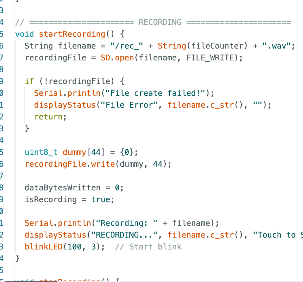
The SPI pins can be assigned in the code to any free pins on the IndusBoard Coin. All GPIO pins are compatible with SPI on the board. Recording starts and stops using the touch pin on the IndusBoard Coin. The code continuously monitors the touch status and initiates audio sampling when triggered. Audio captured from the I2S MEMS microphone is then saved to the SD card.
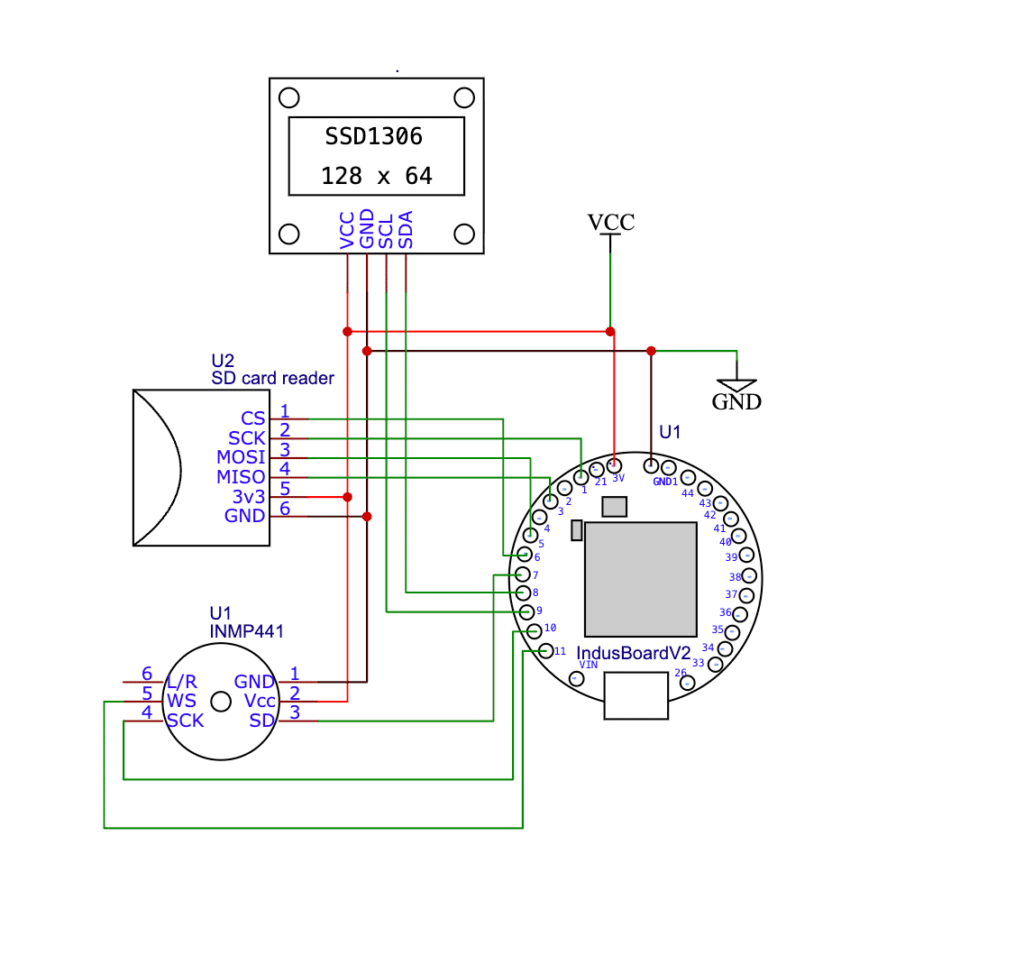
ESP32 Voice Recorder Circuit
The INMP441 microphone is connected using the I2S digital interface for clean, low-noise audio. Its Vcc pin is connected to 3.3V and GND to ground. The microphone’s SCK (Bit Clock) is wired to GPIO10, WS (Word Select/LRCLK) to GPIO9, and SD (Serial Data Out) to GPIO11, while the L/R pin is grounded to select the left channel. This configuration allows the ESP32-S2’s I2S peripheral to sample audio at 16kHz in 16-bit mono format directly without additional amplification.
The microSD card reader uses SPI communication with custom pins optimised for the IndusBoard Coin: CS to GPIO6, SCK to GPIO1, MOSI to GPIO5, and MISO to GPIO3. Both the SD card and OLED share the common 3.3V power supply and ground lines. The SSD1306 OLED is connected via I2C with SDA on GPIO21 and SCL on GPIO22 (default I2C pins), providing real-time status updates during operation.
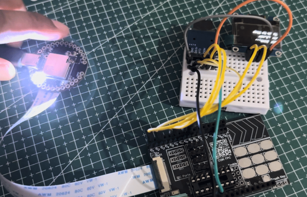
A capacitive touch pad is implemented on GPIO4 for starting and stopping recordings. Additionally, GPIO33 is used as a PWM output to drive an LED that acts as a real-time audio level indicator, brightening according to the sound volume. All components share a common 3.3V power supply and ground. The complete connection can be made as shown in the circuit in Fig 4.
Testing Portable Voice Recorder
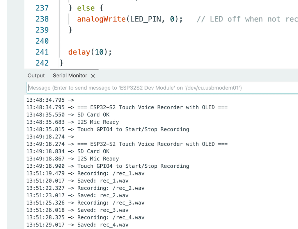
When powered on, the ESP32-S2 initialises the SD card, I2S microphone, OLED display, and calibrates the touch sensor on GPIO4. The system remains in standby mode, showing “Ready” on the OLED. When the user touches GPIO4, recording begins by creating a new WAV file (rec_1.wav, rec_2.wav, etc.). Audio data is continuously read from the INMP441 via I2S, processed with software gain and filtering, and written to the SD card.
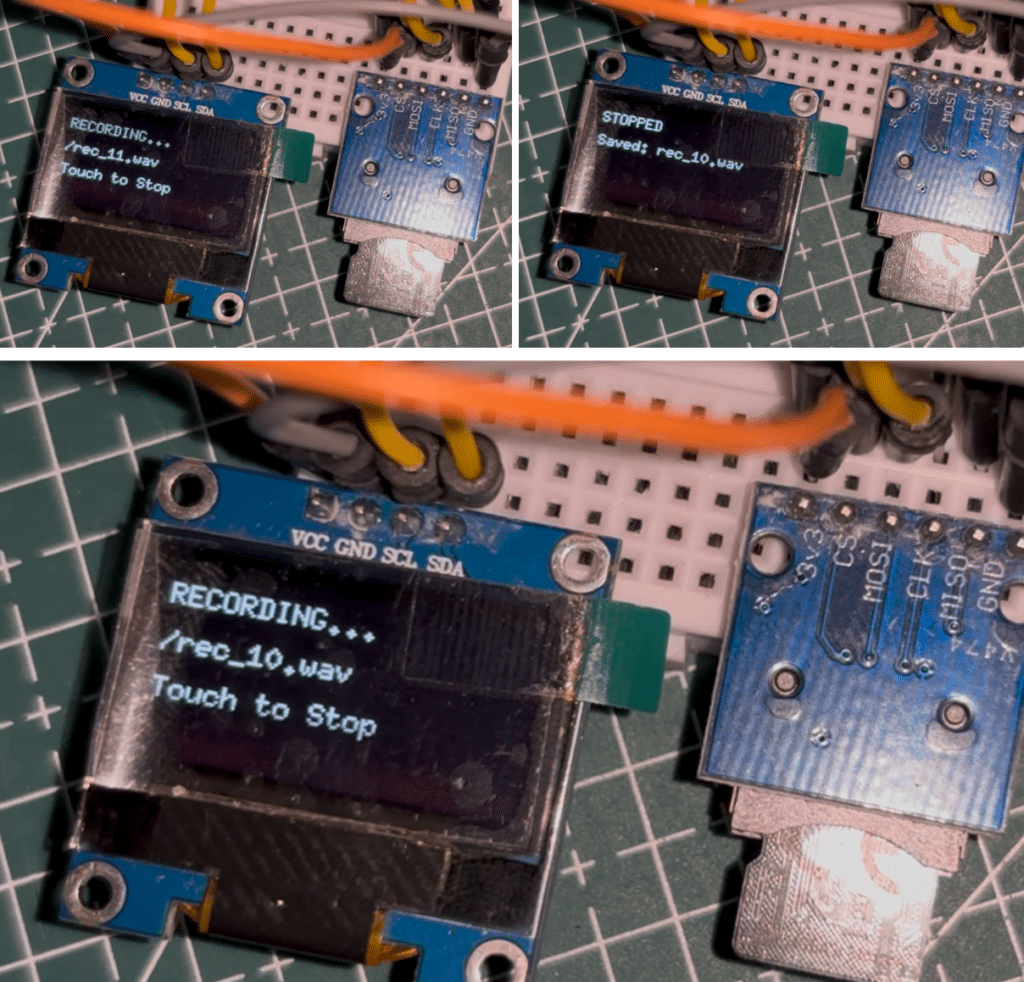
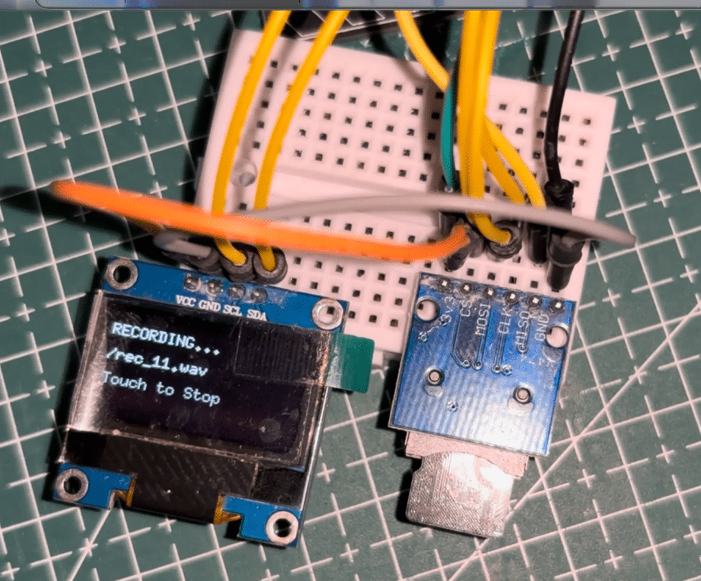
The OLED displays the current filename and a countdown for the minimum 30-second recording duration. The LED on GPIO33 provides visual feedback of the audio level. After the minimum recording duration, touching GPIO4 again stops the recording (refer to fig 7 for the OLED display message during recording and saving), finalises the WAV header with the correct file size, and saves the file.
This results in a clean, portable, and fully functional voice recorder suitable for interviews, surveillance, wildlife monitoring, and machine diagnostics. The recorded voice can be viewed and played on a laptop after connecting the SD card.