


Introduction
The signal from most of the microphones should be amplified before to be send to the interconnection cables.
In order to reduce the noise of the amplifier the bandwidth of the signals is frequently limited to from around 200-300Hz to around 3.3-5kHz.
Modern low cost transistors are giving a lot of possibilities to create low noise band limited to amplifier for microphones.

That short article is proposing simple and effective solution of the problem with low noise microphone preamplifier with limited bandwidth by passive RC filters.
Description of the circuit
Figure 1 is showing the circuits of the transistorized microphone preamplifier with band pass filter.
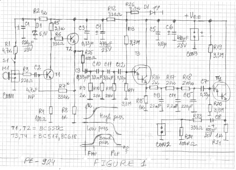
The microphone is connected to the connector CON1.
The switch S1 is closed only of the microphone is need of power supply.
The signal from the microphone M1 is amplified by the first stage built around transistors T1 and T2.
The gain of the first stage is approximately equal to -R5/R4.
It is set usually in the range from 30 to 100.
The collector currents of both transistors are set by the resistor R7.
The circuit has main high pass filter for limiting the frequency range of the input signal.
That filter has three RC networks with the cut-off frequencies listed below:
F1 = 1/(6.28*R9*C9)
F2 = 1/(6.28*R10*C10)
F3 = 1/(6.28*R11*C11)
For the three RC high pass filters usually we have
F high pass = Fhp = F1 = F2 = F3
In that case the cut-off frequency Fhp is selected to be around 260Hz but can have any appropriate Hz but can have any paproprate frequency value.
Also the circuit has main low pass filter.
The filter has three RC networks with 3dB cut-off frequencies listed below:
F4 = 1/(6.28*R16*C13)
F5 = 1/(6.28*R17*C14)
F6 = 1/(6.28*R18*C15)
For thesе three low pass filters usually we have
F low pass = Flp = F4 = F5 = F6
In that case the cut-off frequency Flp is selected to be around 3.6kHz but can have any appropriate Hz but can have any paproprate frequency value.
The transistor T3 is working as buffer between the main high pass and the main low pass filters.
The transistor T4 is working as buffer between the main low pass filter and the output of the preamplifier.
The output is on the connector CON2.
The gain of the stages with T3 and T4 is slightly below unity.
Preferably T3 and T4 are Darlington transistors as BC517 but in some cases selected high gain normal transistors as BC550C, BC109C and similar also will work.
The resistors R13, R14, R19 and R20 are setting the collector currents of T3 and T4.
These resistors should have the maximal possible values in order to be minimal load for the main RC filters built with C9-C11, R3-R11, C13-C15 and R16-R18.
The power supply of the circuit is applied to the connector CON3.
The power supply +Vee should be 9V or above, preferably above 15V.
The circuit will to start to work immediately after the proper montage is done.
The gain of the first stage and the components of the filters are selected according to the needs.
Thank you will make the project and let you know. As I have a microphone and it works on others amps but on my amp 4440 vol on full is 1%