Remote monitoring plays a pivotal role in advancing industrial automation, Industry 4.0, and the Industrial Internet of Things (IIoT).
A remote data monitoring system (RDMS) continuously tracks parameters such as temperature, pressure, humidity, flow, and machine performance real-time.
By collecting data from strategically placed sensors throughout an industrial plant and transmitting it to a centralised hub, this system enhances operational efficiency, reduces downtime, and ensures timely maintenance, thereby boosting overall productivity and safety.

An RDMS proves especially advantageous in large-scale or hazardous environments where manual monitoring is either impractical or risky. It exemplifies the capabilities of modern technology, enabling smarter, safer, and more efficient industrial processes.
A notable example of an RDMS is found in agriculture. Soil moisture, pH, and humidity sensors installed across farms monitor environmental conditions to promote optimal crop health.
The RDMS presented here is a long-range wireless system with a 10.92cm TFT LCD monitor that displays real-time data from three types of sensors using multicolour graphics and animations.
It tracks four environmental parameters: temperature, humidity, ambient light, and soil moisture, and features an impressive range of several kilometres.
As illustrated in Fig. 1, the TFT LCD monitor presents the temperature in degrees Celsius and humidity as a percentage of relative humidity (RH). Ambient light intensity and soil moisture level are both displayed as percentages on a 0-100 scale. The components utilised in this RDMS are detailed in Table 1.
| Table 1: Bill of Materials | |
| Components | Quantity |
| Arduino Uno/Nano (MOD1, MOD4) | 2 |
| Temperature and humidity sensor module DHT11 (S1) | 1 |
| Soil moisture sensor module (S3) | 1 |
| Ambient light sensor LDR (S2) | 1 |
| HC12 module (MOD 2, MOD3) | 2 |
| Resistors 1-kilo-ohm (R1-R6) | 6 |
| Resistors 2.2-kilo-ohm (R7-R12) | 6 |
| Resistors 10-kilo-ohm (R13) | 1 |
| 10.92cm (4.3-inch) SPI TFT LCD monitor | 1 |
| 5V regulated power supply | 2 (for transmitter and receiver) |
| Jumper wires and wires | Based on requirement |
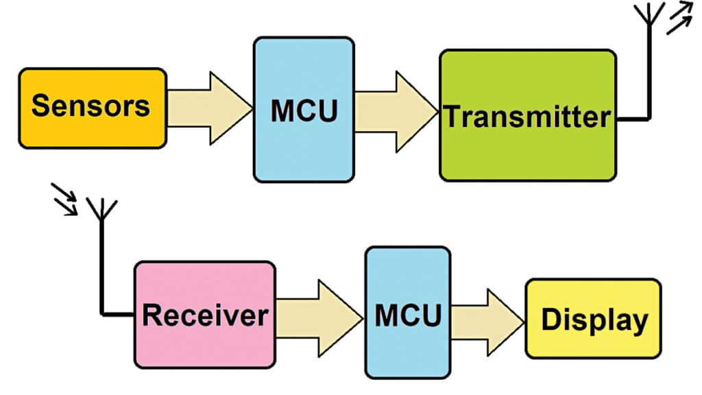
The RDMS comprises both a data transmitter and receiver, as shown in Fig. 2. The transmitter includes one or more sensors (either identical or different), a microcontroller (MCU), and a radio transmitter. The receiver features a radio receiver, an MCU, and a TFT LCD monitor.

Circuit and Working
The operation of the remote data transmitter and receiver in the RDMS is described below.
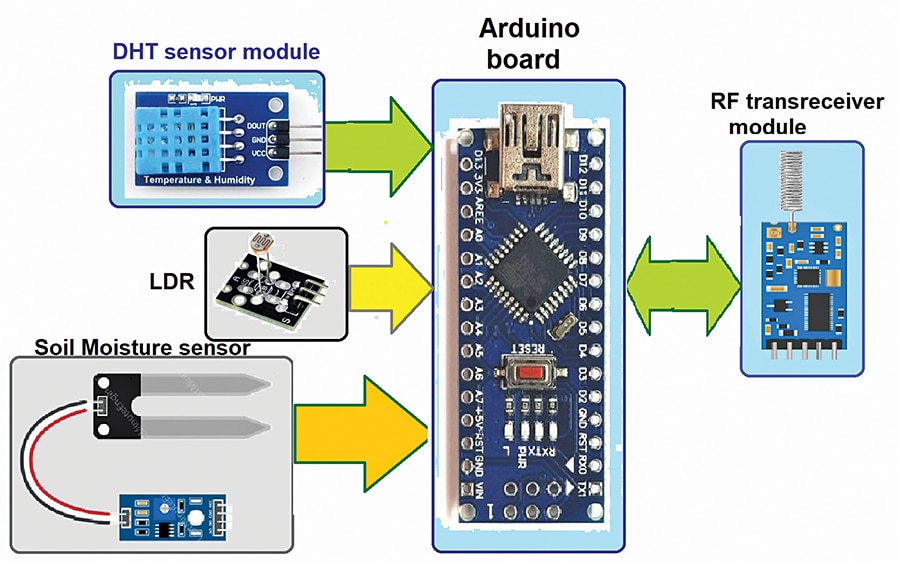
RDMS transmitter: The remote data transmitter consists of three different sensors, an Arduino Nano board as the MCU, and an RF transceiver module. The primary components of the transmitter include the DHT11 sensor, LDR sensor, and soil moisture sensor module, which measure temperature and humidity, ambient light, and soil moisture, respectively. The block diagram of the transmitter is shown in Fig. 3.

Circuit diagram of the RDMS transmitter: The circuit diagram of the data transmitter is presented in Fig. 4. The transmitter circuit is constructed using the DHT11, LDR, soil moisture sensor module, a 10-kilo-ohm resistor, an HC12 RF transceiver, and an Arduino Nano board (MOD1).
First, connect a 5V power supply to MOD1 externally after uploading the source code. Then, connect all components as shown in Fig. 4. The DHT11 sensor has three interfacing pins: VCC, GND, and DATA. The VCC pin connects to the 5V output pin of MOD1, the GND pin to the circuit ground, and the DATA output pin to the digital D2 pin of MOD1.


Very useful project , students can gather a lot of knowledge and hands on experience on real life data monitoring using Arduino after going through it .