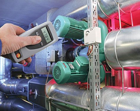
Low-cost, high-value sensor options are available for revolutions-per-minute (RPM) measurement applications. Most of these sensors provide simple, reliable and inexpensive transducers for highly sophisticated control systems.
Take a look at different types of tachometers for RPM measurement, advanced sensor modules, frequency measurement, and period measurement methods.

Table of Contents
Detecting the stoppage of a rotating shaft (zero-speed detection) is significant in many applications, for example, to determine whether a conveyor has failed. Revolutions per minute (RPM) measurement is crucial when controlling or monitoring the speed of motors, conveyors, turbines, etc.
RPM is a measure of the frequency of a rotation. It annotates the number of full rotations completed in one minute around a fixed axis. It is used as a measure of the rotational speed of a mechanical component.
Advanced electronics technology now offers low-cost, high-value sensor options for RPM measurement applications. Most of these sensors provide simple, reliable and inexpensive transducers for highly sophisticated control systems.
RPM Sensors
A sensor is essential to sense shaft speed. Typically, devices used for this purpose are shaft (rotary type) encoders, photoelectric (optical type) sensors and magnetic rotational speed (proximity type) sensors.
All of these sensors send speed data in the form of electrical pulses. Shaft encoders offer a high resolution of typically 1-5000 pulses per revolution (PPR) and clearly defined, symmetrical pulses.
Proximity sensors provide medium (or low) resolution sensing, depending on the number of pulses measured per revolution. Photoelectric sensors usually sense a reflective target on the rotating shaft.
Magnetic rotational speed sensors use various magnetic proximity measuring principles to monitor the speeds of machine components in a range between 0 and 30,000 rpm.
In principle, RPM sensors convert mechanical motion into electric pulses with or without direct contact when positioned near a turning rotor, gear, shaft or other regularly moving device. The resultant output signals are then fed to a digital counter, totaliser, tachometer, or other monitoring and control device.
Tachometers
The word ‘tachometer’ is derived from the Greek words ‘tachos,’ meaning ‘speed,’ and ‘metron,’ meaning ‘to measure.’ A tachometer is a device designed to measure rotational or surface speed either in contact or non-contact way.
Tachometers are widely used to measure the rotational speed of motors, conveyor belts, and other moving or rotating systems.
RPM measurement with a tachometer can simply be divided into three popular methods:
Mechanical
In this method, revolutions in the mechanical sensor are electronically analysed in the instrument. This good old method is still commonly used for low resolutions between 20 and 20,000 rpm. Mechanical tachometers utilise the fact that the centrifugal force on a rotating mass depends on the speed of rotation.
Optical
Here rotation is transmitted to the measuring instrument via an infrared (IR) light beam/laser beam coming from the instrument, which is then reflected by a reflective tape on the object.
As explained, traditional tachometers require physical contact between the instruments and the objects being monitored. Laser tachometer is a powerful choice where this type of direct-contact type measurement is not workable for technical or safety reasons.
Laser tachometers work by pulsing a laser beam against the rotating element. The rotating element will have one reflective spot, and the tachometer measures the rate at which the light beam is reflected back.

Stroboscopic
It has clear advantages over other measuring methods using mechanical or optical sensors. According to the stroboscopic principle, objects are stationary in the eyes of the observer when the frequency of high-speed flashes is in synchronisation with the RPM of the object.
A stroboscopic light source provides high-intensity flashes of light, which can be caused to occur at a precise frequency. When this light source is made to fall on an object with periodic motion, it appears that the motion has slowed down or stopped when both frequencies bear a definite relationship.
Stroboscopic tachometers employ this effect for RPM measurement. Mechanical RPM measurement is not good for small objects.
Although the optical method is superior to the mechanical method, practically it is not always possible to bond reflective tapes on objects. But with the stroboscopic method, measuring the RPM of even very small objects is always possible.
Sensor Modules for Unique Speed-Sensing Solutions
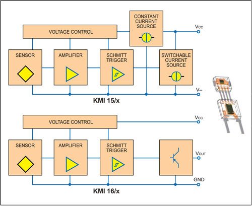
Today’s advanced sensor modules (and sensing techniques) provide simple and cost-efficient solutions for rotational speed measurement in many applications including automotive, industrial and medical.
Variable Reluctance Speed Sensor
A variable reluctance (VR) sensor is composed of a wire wound around a cylindrical magnetic material, typically made of some type of ferrous material that is referred to as a pole piece. A magnet is attached behind the pole piece, creating a magnetic field through the pole piece and winding.
This magnetic field projects out from the pole piece front, also known as the sensor tip. When ferrous material passes through and disrupts this magnetic field, a sine wave is generated. The frequency of the signal is directly proportional to the speed of rotation.
VR speed sensors are passive devices that do not require any external source of power to generate a signal.
Note that a variant of the VR sensor is available as an inductive magnetic sensor. It differs from the standard VR sensor in that the magnet is not in the unit but in the object being sensed. Inductive magnetic sensors are used when the rotating device sensed cannot be made of ferrous materials.
Magnetoresistive Speed Sensor
Rotational speed measurement using a magnetoresistive (MR) sensor is achieved by counting ferromagnetic marks, such as teeth of a passive gear wheel or the number of magnetic elements of a magnetised ring.
Magnetoresistive sensors make use of the magnetoresistive effect—the property of a current-carrying magnetic material to change its resistivity in the presence of an external magnetic field.
Although inductive sensors can be used for this task, magnetoresistive sensors have the advantage that the output signal level does not vary with rotation speed, as in the case of inductive sensors.
MR sensors are static and the output signal is generated by the bending of magnetic field lines according to the position of the target wheel. As bending of the magnetic field lines also occurs when the target is not moving, these sensors can measure very slow rotations, even down to zero hertz (0 Hz).
However, note that MR sensors cannot directly measure rotational speed, but are sensitive to the motion of a toothed wheel made from ferrous material (passive target, a sensor fitted with a permanent magnet) or a rotating wheel having alternating magnetic poles (active target).
RPM Measurement Techniques
Frequency measurement and period measurement are two widely accepted methods for determining RPM. Frequency measurement is better for fast-moving devices such as motors and turbines, while period measurement is better for devices that move more slowly, such as shafts.
When using frequency measurement as a method of monitoring RPM, the key factor is the number of pulses being sensed per revolution (PPR). This method works well with high-PPR sensors and works poorly for low-PPR sensors.
When using the frequency measurement method, you can calculate the RPM using this equation:
RPM = (Pulse Frequency in pulses/sec)×(60 sec/min)/(Sensor pulses/revolution) = Revolutions/Minute
This equation shows the relationship between frequency and period as:
Frequency = 1/Period
When using period measurement to monitor RPM, the RPM can be calculated by using the equation:
RPM = 60/Pulse period x PPR
In addition, note that the frequency method is good for zero-speed detection. If you use the frequency method to monitor the RPM, you can know the shaft has stopped when the frequency being sensed drops to zero.
On the other hand, if you use the period method, the main issue is determining how much time to allow between pulses before deciding that the shaft has stopped. Basically, this method requires a little more complex logic!
From Printing to Life Care!
Rotational speed sensors are widely used to monitor the speeds of machine components, from printing and paper machines to aircraft, ships and wind turbines. A tachometer can even find uses in medicine to diagnose circulatory problems such as clogged arteries.
By placing a small, turbine-like device called haematachometer in an artery or vein, doctors can use a tachometer to interpret the rate of blood flow from the speed at which the turbine spins.
Nowadays, innovative rotational speed sensor technology offers a wide range of standard products for the most varied applications, with suitable measuring systems and electronics, as well as appropriate housings, designs and connections.
The design trend is towards the fabrication of tiny chips, i.e., chips integrated with sensor bridges, signal amplifiers, gain controls, differential analogue line drivers and digital interface circuits, for contactless RPM measurement, position control/sensing and rotating angle measurement, etc.
The author is a regular contributor to EFY


Hello , We have a requirement of RPM sensor for motor shaft , Can you please suggest the right one along with specs and pricing
Hello , We have a requirement of RPM sensor for motor shaft , Can you please suggest the right one along with specs and pricing
Hello ,
please someone can guide me how to calculate the rpm of an equipment for example a feeding screw attached with a gear motor while motor rpm is provided??
Can anybody suggest right sensor to monitor speed of 12000rpm to 15000rpm