


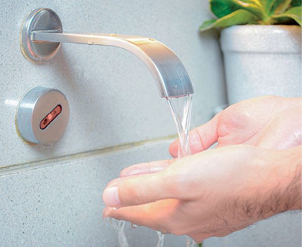
Infrared (IR) water faucets (touch-free faucets) look modernistic, and can significantly increase the style level in a luxurious bathroom. Nowadays, IR water faucets are widely used in hospitals and in other areas with industrial or public sanitary installations because traditional water faucets can collect bacteria and viruses, as these are constantly being touched by many different people. Further, IR water faucets are a proven solution to save water.
System overview
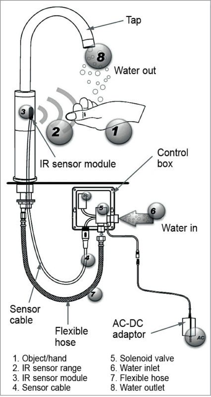
Although it looks like a sleek accessory in a stylish bathroom, there is a lot happening under the sink with an IR water faucet. In principle, an IR water faucet combines four key components: IR sensor module, solenoid valve, control box and power source.
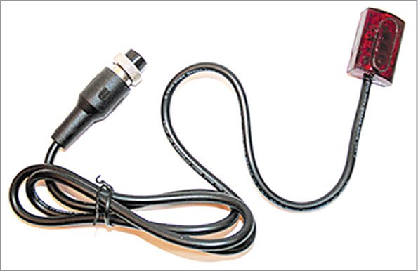
IR sensor module
An IR sensor module is usually visible and looks like a small lens on the front of the faucet. The sensor module (covered by a plastic IR sensor shell) holds one transmitter component and one receiver component.
The transmitter (usually an IR LED) continuously emits invisible light to scan whether there is an object in front of the water faucet. If a hand, for instance, enters within the range, it reflects the transmitted IR light. The receiver (usually a photodiode or phototransistor) recognises this and opens the solenoid valve with the help of associated controller electronics.
In short, if the sensor feels the presence of an object in front of the tap, it actuates the solenoid valve to initiate the flow of water. When the object is no longer present, it deactivates the solenoid valve to terminate the water flow, usually after a few seconds.
Solenoid valve

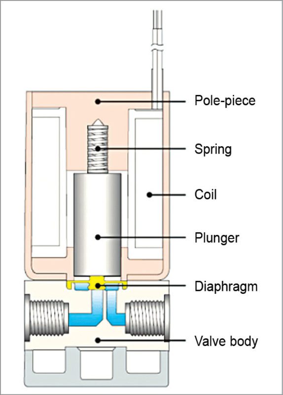
A solenoid valve physically starts and stops the water flow by transforming electrical energy into motion. A standard solenoid valve allows water flow when DC supply holds a plunger at its open position. In the absence of DC supply, the plunger returns to its initial (closed) position to prevent the flow of water.
Note that, pulse-type (latching-type) solenoid valves are also used in today’s IR faucets. Here, the solenoid valve is initially pulsed to start the water flow (plunger is driven into the vicinity of a permanent magnet, which, in turn, holds the plunger in open position). In order to return the plunger to its closed position, the solenoid valve is once again pulsed, but this time with a reverse-polarity signal.
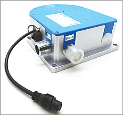
Control box
A control box is like a control hub that sits or is mounted underneath the sink as part of a typical IR water faucet installation process. The control box is a rigid, water-proof enclosure that accommodates almost all requisite components/parts (except IR sensor module) like solenoid valve, electronic control circuitry and power source. Most control hubs can be powered by built-in battery packs or by mains via external AC-DC power adaptors.
Overview breakdown
IR water faucets are created by combining the four key components. Although there are variations, key components, each with a distinct function, once combined, constitute an IR water faucet. Here is an overview breakdown of the components:
1. IR water faucets employ presence sensors (not motion sensors) to sense the presence of an object in front of the faucet. These employ active IR technology that senses presence, and not movement, of objects. Active IR technology, like the name implies, actively emits IR light and actively waits for this light to come back to it.
2. Based on sensor feedback, the electronic control circuitry commands the solenoid valve to start/stop the flow of water.
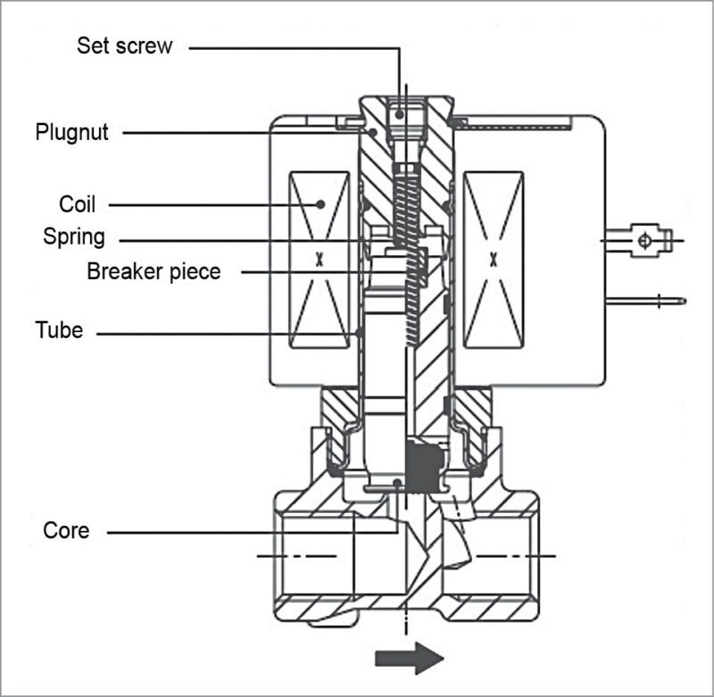
3. Faucets powered by AC transformers utilise standard solenoid valves. Such solenoid valves require constant energy to hold the plunger in place, and when e-energised, the plunger naturally returns to its normal closed position with the help of a biasing spring.
On the other hand, faucets powered by batteries employ another type of solenoid valve called pulse or latching solenoid valve. These solenoid valves operate at low voltage, usually 6V DC, with some solenoids operating at 9V DC.
The reason these solenoids are called latching type is that, as the solenoid is initially energised to start the water flow, the plunger is driven into the range of a permanent magnet, which, in turn, holds the plunger in open position. This initial energising of the solenoid is called pulsing and takes place within a fraction of a second. In order to return the plunger to its original closed position, the solenoid is once again pulsed, but this time by reversing polarity. This complex operation, however, can conserve battery power.
4. The solenoid valve physically controls the start and stop of the water flow through the faucet spout. The solenoid valve is, in fact, a perfect blend of two hybrid technologies—electromagnetism (solenoid) and fluid dynamics (diaphram valve).
A solenoid is an electrical component that transforms electrical energy into mechanical energy—motion. When energised, it creates a magnetic field that exerts a linear force on an object called plunger. The basic premise behind the diaphragm valve is to control the flow of a large volume of water with a smaller, more manageable water volume. In order to open the diaphragm valve, there is need to release the pressure that is pinning the diaphragm against the valve seat—this is the job of the solenoid valve.
The plunger, which is driven by the solenoid, is yet another miniature water valve whose sole mission is to open and release the pressure that is pinning the diaphragm against the valve seat. It closes and allows the pressure supplied through a very small diameter hole to build up behind the diaphragm, pinning the diaphragm back against the valve seat.
5. Proportional solenoid valves are a newcomer in the solenoid valve family. Most solenoid valves work on an on/off basis, and are either fully-open or fully-closed. Proportional solenoid valves, however, operate with a proportional action. By varying the electrical input to a proportional valve, the flow of water through the valve can be continuously and steplessly adjusted between zero and 100 per cent of the maximum rated flow. In order to obtain the proportional action, the solenoid operator is modified.
Proportional solenoid valves operate on the principle that the pull force produced by an electromagnetic coil increases as coil current (Is) is increased, while, likewise, the counter-acting spring force increases when the top spring is compressed.
(a) If the current is less than Io*, preset tension of spring Fs is greater than electromagnetic pull force Fm and the valve remains closed.
(b) If current increases to above Io, Fm is greater than Fs and the core starts to move. Movement of the core compresses the spring, causing Fs to increase. This continues until the new values of Fs and Fm are once again in balance. The process continues so that at any value of I, the core moves into a position where Fs and Fm are balanced. Specific parts of a proportional solenoid valve are shown in Fig. 7.
[*A proportional solenoid valve can be made to open or close infinitely by regulating the current (Is) flowing through the solenoid coil. Coil current (Is) is mainly regulated by regulating the voltage (Us) across the coil. Voltage across the coil can be derived from various supplies, for example, a straight DC supply or a pulse-width modulated supply.
In order to maintain the valve in a specific position, coil current (Is) should be kept substantially independent of changes in the coil-winding resistance due to temperature variations (caused by power input and ambient temperature) typically between 100mA (Io) and 500mA (Imax).]
6. Both the sensor/controller electronics as well as the solenoid valve require a power source. Often, standard battery packs are used as the power source. Commonly-used batteries are C, AA, 6V and 9V lithium batteries. Even so, automatic faucets using an AC transformer as the power source are relatively cheaper than their battery-powered counterparts.
7. Most IR faucet spouts (for water delivery) are designed to house the IR sensor module within these, or fibre-optic sensor capsule to carry the IR signal from the sensor to the spout. Some trendy spouts house the whole sensor, control electronics, solenoid valve and the AC/DC power supply unit within these.
IR water faucets reflect a great combination of innovative design and advanced technology. There are many models in modern designs that go well with other modern accessories and fittings for bathrooms. Like all traditional faucets, you can get IR water faucets in multiple designs and materials.
Generally, IR water faucets are easy to care for and need little maintenance. If you use a type with batteries, you will need to change these when these run out of power. Electronic components can fail in rare cases, but you can simply replace the whole electronic assembly at once, if required. Apart from some little issues that might come up every few years, if these do at all, IR water faucets should not require any further maintenance.
T.K. Hareendran is founder and promoter of TechNode Protolabz
