


Before we dive deep into the 8051 microcontroller, let’s first explore the fundamental components: the microcontroller itself, the CPU (central processing unit), memory, and the bus system that enables communication between these elements.
Microcontrollers: It is a programmable integrated circuit (IC) that consists of a small CPU, RAM and I/O pins. Microcontroller units (MCUs) are widely used in many devices.

Check the difference between Microprocessor and Microcontroller
CPU: It performs processing and is considered the mind of the microcontroller. By giving instructions to the MCU, one can communicate with the I/O pins and control them as per needs.
Memory: It stores the instructions and data required by the microcontroller.
Bus: It acts as a communication medium between components for data transfer.
Table of Contents
8051 Microcontroller
After the first 8051 microcontroller was designed by Intel in 1980, several powerful variants were made by adding ADCs, Op Amps and more.
Along with these, the 8051 microcontroller had a 16-bit address bus for data transfer accompanied by an 8-bit data bus for carrying data for particular applications.
The current microcontroller belongs to the 8-bit family of microcontrollers and is packed with 128Kb of RAM, 4Kb of ROM, 4 ports, 2 timers and 1 serial port all on a single chip. These chips can easily be programmed using assembly language.
Applications
The 8051 MCUs are widely used in embedded systems, aeronautics, space technology, transportation management systems, robotics, communication, automotive and in many various fields.
These ICs can be used in a variety of embedded applications for different projects involving electronics and robotics. Some are:
- Moving Message LCD Display
- Fuel Theft Alarm
- Water Level Indicator
- RF Based Multipurpose Device
- Microcontroller-based Tachometer
- Microcontroller-based Tone ring player
- Microcontroller-based Thermometer
Pinouts and Functions of 8051 Microcontroller
The 8051 comes in a Dual Inline Package (DIP ) and consists of 40 pins i.e. 20 pins on both sides of the MCU (as shown in the pic. below).
All these 40 pins have been specified for different purposes and I/O functions like analogue/digital read-write, interrupts and serial communication.
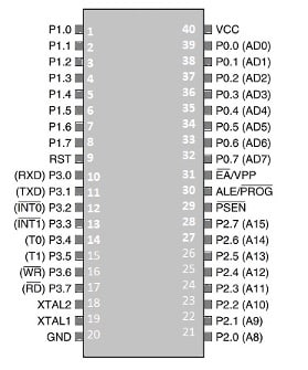
| PINOUTS | FUNCTIONS |
| Pins 1-8 | These are referred to as port 1 pins and are used for executing simple I/O operations. These pins can be configured by changing their logic state to 0 or 1. |
| Pin 9 | This is known as the RESET pin for resetting the microcontroller. To terminate a running activity of the microcontroller, this pin can be used. |
| Pin 10-17 | These are referred to as port 3 pins. Similar to port 1 pins, port 3 pins are used as universal input-output port along with executing a few more functions as described below from Pin 3.1 to 3.7 |
| P3.0 (RXD) | This is a serial pin for receiving data. It is used for establishing serial communication to receive data through the input signal. |
| P3.1 (TXD) | This is also a serial pin. It is used for data transmission through the output signal via the serial port. |
| P3.2 and P3.3 | These pins are used for external hardware interrupts. |
| P3.4 and P3.5 (T0 and T1) | These are timer pins that can be connected with a 16 bit counter. |
| P3.6 | This is a memory write pin for writing data to external memory. |
| P3.7 | This is an external memory read pin for reading the data from external memory. |
| Pin 18 and 19 | These are the pins for external oscillators and can be connected to quartz oscillators to provide external clock frequency. |
| Pin 20 | This is the ground (GND) pin for connecting the GND (negative) wire of sensors and modules used with the microcontroller. |
| Pin 21 to 28 | These are referred to as port 2 pins. They are bidirectional and used for interfacing the external memory with the microcontroller |
| Pin29 | This pin is known as Program Store Enable (PSEN). It is used for reading the external memory. |
| Pin 30 | This pin is known as Address Latch Enable (ALE ). It is used for distinguishing the addresses of multiple memories. |
| Pin 31 | This pin is known as External Input (External Access) input. It is used for enabling and disabling the external memory interfacing. |
| Pin 32 – Pin 39 | These are port 0 pins. They are also bidirectional and used as an I/O port. |
| Pin 40 (VCC) | It is a pin for supplying power to circuits with +5V. |
8051 Architecture
The 8051 processes 8-bit data and is an 8-bit microcontroller. Here is the block diagram showing microcontroller architecture. According to it, the 8051 consists of a CPU, RAM, Flash Memory (EEPROM) and I/O.
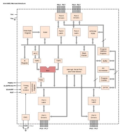
Their peripherals communicate using the internal data bus that is an 8-bit data bus.
8051 Microcontroller Features
- 8-bit CPU with two registers A (ACC or accumulator) and B
- Internal Flash ROM of 8KB
- 32 I/O
- Internal RAM of 256 bytes
- 8-bit Stack Pointer
- 16-bitProgram Counter and Data Pointer (DPTR)
- Two 16-bit timers, T0 and T1
- Two external and three internal interrupts
- Oscillator and clock circuit
- Serial Data Receiver Transmitter
For more information on 8051: click here
Microcontrollers come in handy for several Top Microcontroller Projects like ATmega16A Based GPS Receiver, GPS- and GSM-Based Vehicle Tracking System, Ultrasonic Radar Microcontroller Project, etc.
The 8051 microcontroller remains a popular choice for a wide range of embedded systems projects. Its simple design, ease of use, and robust capabilities make it ideal for everything from robotics to automotive applications.
If you’re planning to start a project or have any questions, feel free to comment below. We’re here to help you bring your ideas to life!