


In an astable circuit, the output voltage alternates between VCC and 0 volts on a continuous basis.
Inputs
Outputs
The Astable 555 Timer Calculator simplifies the process of designing and analyzing a stable 555 timer circuits by providing quick and accurate calculations based on user-input component values.
By entering the values of the capacitor, resistance 1, and resistance 2, users can obtain essential timing parameters such as frequency, period, duty cycle, and more.

Input Parameters:
- Capacitor (C): The value of the timing capacitor in farads (F).
- Resistance 1 (R1): The value of the first external resistor in ohms (Ω).
- Resistance 2 (R2): The value of the second external resistor in ohms (Ω).
Outputs:
- Frequency (f): The frequency of the output square wave signal, measured in Hertz (Hz).
- Period (T): The period of the output waveform, representing the time taken for one complete cycle, measured in seconds (s).
- Duty Cycle: The ratio of the duration of the signal’s high state to the total period, expressed as a percentage.
- Mark Space Ratio: The ratio of the duration of the signal’s high state to the duration of the signal’s low state.
- Time High (T1): The duration of the signal’s high state, measured in seconds (s).
- Time Low (T0): The duration of the signal’s low state, measured in seconds (s).
Astable 555 Timer Formulas
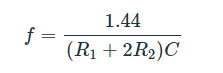
The frequency is the number of pulses per second. The formula to calculate the frequency of the output voltage is:
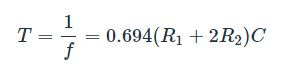
The period is the time covered for one pulse. This is just the reciprocal of the frequency:
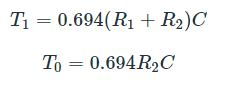
The high time (T1𝑇1) and low time (T0𝑇0) can be calculated using the formulas below. Note that the period is the sum of the high time and the low time.
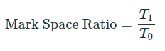
The mark space ratio is the ratio between the high time and the low time or:
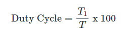
The duty cycle is more commonly used than the mark space ratio. The formula for the duty cycle is:
A 50% duty cycle means the high time is equal to the low time. If an LED is placed at the output of this astable circuit, it will turn on at the same span of time as it is turned off.
Note:
- Getting an exact 50% duty cycle is impossible with this circuit.
- Increase C to increase the period (reduce the frequency).
- Increase R1 to increase High Time (T1), without affecting the Low Time (T0).
- Increase R2 to increase High Time (T1), increase Low Time (T0) and decrease the duty cycle.
Also check: 555 Timer Monostable Circuit Calculator
Check Electronics For You’s Electronics Calculators that you can use for free.