


Do you face problems like power faults and surges in designing PLC systems? See how this reference design can help you resolve the issue.
Designing a Programmable Logic Controller (PLC) system can be a very tedious task for the design engineers since continuous operation and reliability are critical with PLCs. You might encounter some input power faults such as overvoltage, undervoltage, overload, inrush currents, and reverse polarity. This can quickly damage sensitive components like Central Processing Units (CPUs), Input/Output (I/O) modules, and communication modules.
In addition, screw-type connectors commonly used in industrial setups make it easy to accidentally connect power in reverse, increasing the risk of system failure. You as an engineer must also ensure that PLCs can survive common industrial disturbances, including electrostatic discharge (ESD), burst pulses, surge events, and voltage dips or interruptions, while maintaining uninterrupted operation.
At the same time, backup power is essential to prevent system downtime during short-term power failures, giving the CPU and critical modules enough time to shut down safely or maintain minimal operation. Achieving all of this typically requires a careful combination of protection and backup circuitry, often involving multiple discrete components, which increases board complexity, cost, and design time. TIDA-03031, a reference design from Texas instruments (TI) claims to replace traditional circuits with fully integrated solutions.
This design is suitable for PLC, DCS, and PAC systems, including CPUs, I/O modules, and communication modules. It is also applicable in CNC automation controller units and other backup power supply applications. By integrating protection and backup functions, you can simplify designs, reduce component count, and ensure compliance with industrial standards.
The electronic fuse (eFuse) handles input protection, including overvoltage, undervoltage, overload, inrush current control, reverse current, and reverse polarity. It provides monitoring functions such as fault status and load current output. For backup supply, the boost converter charges a bulk capacitor in discontinuous mode (DCM), taking about 0.4 seconds to fully charge. The integrated buck regulator steps down the bulk capacitor output to 17 V. During normal operation with a 19.2–28.8 V input, the buck regulator output is above regulation voltage, so switching is disabled. It only activates when the input drops below the regulation voltage.
During a power failure, the eFuse de-asserts the fault output (FLTb) signal and disables boost switching. The bulk capacitor momentarily supplies full-load current until the buck regulator takes over. The FLTb signal informs the Programmable Logic Controller (PLC) Central Processing Unit (CPU) of the power-fail event, allowing the CPU to initiate extended backup if needed.
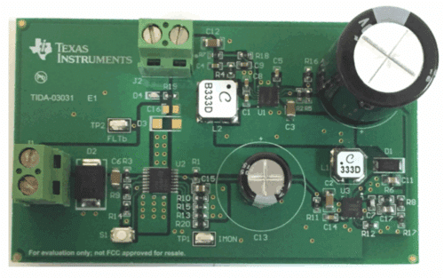
TI has tested this reference design. It comes with a bill of materials (BOM), schematics, assembly drawing, printed circuit board (PCB) layout, and more. The company’s website has additional data about the reference design. To read more about this reference design, click here.