


This project demonstrates a low-cost intelligent traffic signal system using Arduino and ultrasonic sensors to reduce congestion caused by fixed-timer traffic lights. Four HC-SR04 sensors detect vehicle presence in real time across four lanes. If a vehicle is detected, the lane gets a 10-second green signal; if not, the green phase is limited to 2 seconds. The two Arduino boards communicate via I2C, and RGB LEDs simulate traffic lights. The modular design improves traffic flow during uneven traffic conditions and can be easily scaled or upgraded with IoT features.
Efficient traffic management in urban areas remains a significant challenge as vehicle density grows and infrastructure struggles to keep pace. Conventional traffic lights rely on fixed timers, which often result in unnecessary delays and congestion during low-traffic periods. To address this, an intelligent traffic signal control system has been developed using low-cost, readily available components, including Arduino Uno and Arduino Nano boards and HC-SR04 ultrasonic sensors. Four ultrasonic sensors continuously monitor vehicle presence across four lanes. The sensor unit (Arduino Uno) collects proximity data and sends it via I2C communication to the control unit (Arduino Nano), which adjusts signal timing in real time.
POC Video Tutorial
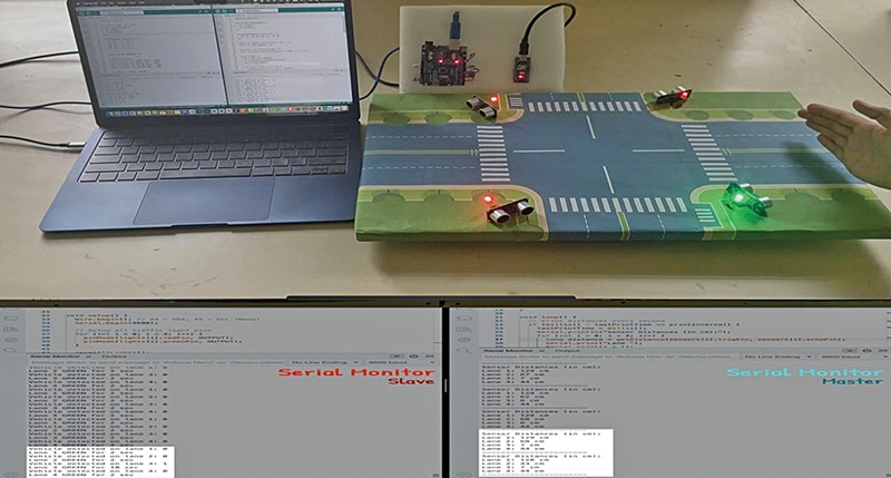
When a vehicle is detected in a lane, that lane receives a 10-second green light. If no vehicle is present, the green phase is limited to a pre-timed 2 seconds. After the green interval, the signal automatically switches to red, and the system advances to the next lane. The distance readings from each lane are updated on the serial monitor every second.
RGB LEDs indicate the traffic signal status (green/red), and the system logs its control sequence through the serial monitor. The modular, low-cost architecture enables straightforward scaling for additional lanes or future IoT enhancements. Fig. 1 presents a prototype of the system setup, and Fig. 2 provides the corresponding block diagram.
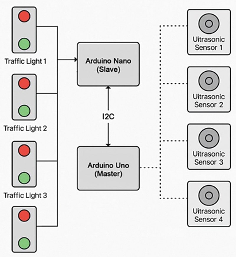
Two Arduino boards are used in the system. One functions as the sensor device and the other acts as the controller device. Both communicate over the I2C line. The sensor device detects vehicles using ultrasonic sensors, while the controller operates the RGB LED for signal indication. These components form the core of the system design. The required components are listed in Table 1 for the Bill of Materials.
| Table 1: Bill of Materials | ||
| Component | Quantity | Description |
| Arduino Uno R3 (MOD1) | 1 | Control unit (master) |
| Arduino Nano (MOD2) | 1 | Sensor unit (slave) |
| HC-SR04 ultrasonic sensor (U1-U4) | 4 | Distance sensing for each lane |
| RGB LEDs (common cathode) (LED1-LED4) | 4 | Red and green signal simulation |
| Jumper wires | 30+ | Wiring between boards and components |
| Breadboard | 1 | For mounting and layout |
| USB cable (mini type B) | 1 each | Programming and powering the boards |
Table 2 summarises the signal behaviour of the smart traffic control system based on real-time vehicle detection. It outlines how the system dynamically adjusts the durations of the green and red LED indicators based on traffic conditions in each lane.
| Table 2: Condition-Behaviour Correlation | |||
| Condition | Signal Phase | Duration | LED Behaviour |
| Vehicle detected | Green | 10 seconds | Green on, red off |
| Vehicle not detected | Green | 2 seconds | Green on, red off |
| After green (transition) | Red (all lanes) | 2 seconds | Red on, green off |
| Other lanes (idle) | Red | Until the cycle repeats | Red on, green off |
Traffic Light Controller: Design, working, and setup
The system has been developed as a dynamic traffic signal control system using Arduino Uno and Arduino Nano, designed to operate based on real-time vehicle detection across four lanes. HC-SR04 ultrasonic sensors detect vehicle presence and RGB LEDs simulate traffic signals. Communication between the two Arduino boards is established via the I2C protocol, ensuring coordinated sensing and signal control. The setup demonstrates intelligent lane management using low-cost and widely available hardware components.
The system is divided into two functional units: the sensor unit (Arduino Uno, master) and the control unit (Arduino Nano, slave).
In the sensor unit, the Arduino Uno (master) continuously reads distance values from four ultrasonic sensors, each allocated to one lane. Vehicle presence is determined by comparing the measured distance against a fixed threshold of less than 15cm. The detection status for all four lanes is encoded into a single byte and transmitted to the control unit via I2C communication.
In the control unit, the Arduino Nano (slave) continuously receives detection data from the Uno and determines the traffic signal duration for each lane. If a vehicle is detected in a lane, the Nano activates the green LED for 10 seconds. If no vehicle is detected, the system provides a brief 2-second green phase to minimise unnecessary waiting. During this time, all other lanes remain red. The process cycles through all four lanes, dynamically optimising the signal timing in response to real-time traffic flow.
This intelligent timing approach reduces idle waiting periods at intersections and enhances traffic efficiency, particularly during uneven or fluctuating traffic conditions.
Traffic Light Controller Circuit Diagram
The complete circuit diagram of the proposed system is shown in Fig. 3. It is built around an Arduino Uno, an Arduino Nano, four ultrasonic sensors, four common-cathode RGB LEDs, and a few other supporting components. The Arduino Uno and Nano communicate through the I2C interface using pins A4 (SDA) and A5 (SCL). The controller (Arduino Nano) receives sensor data via I2C and controls the RGB LEDs accordingly to simulate the traffic signal operation.
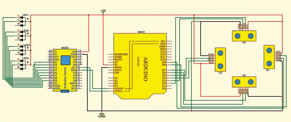
There are two types of RGB LEDs available in market: common cathode and common anode. Their wiring differs accordingly. For a common-cathode RGB LED, the common pin is connected to GND, while for a common-anode RGB LED, it is connected to VCC. In this system, common-anode RGB LEDs have been used; therefore, the common terminal is connected to VCC. Table 3 explains the connections and functions of the various components used in the system.
| Table 3: Connections among the various components | ||||||||
| Arduino Uno | Ardino Nano | Sensor U4 Lane 1 | Sensor U3 Lane 2 | Sensor U3 Lane 3 | Sensor U1 Lane 4 | RGB | 5V | GND |
| D2, D3 | Trig, Echo | MOD1-GND | ||||||
| D4, D5 | Trig, Echo | |||||||
| D6, D7 | Trig, Echo | |||||||
| D8, D9 | Trig, Echo | |||||||
| D2 D3 | R – LED1 G – LED1 | LED1-C | MOD2-G | |||||
| D4 D5 | R – LED2 G – LED2 | LED2-C | ||||||
| D6 D7 | R – LED3 G – LED3 | LED3-C | ||||||
| D8 D9 | R – LED4 G – LED4 | LED4-C | ||||||
| SDA, SCL | A4, A5 | |||||||
| GND | GND | GND | GND | GND | GND | GND | ||
| 5V | 5V | 5V | 5V | 5V | 5V | 5V | 5V | |
Traffic Light Controller Code


I download the source code of this project at Source Code Of EFY’s DIY Projects – Electronics For You – Official Site ElectronicsForU.com. In this project two codes are used for Arduino Uno and Arduino Nano. On the website, Arduino Nano (controller) is not available. Please update.
Hi, thank you for your comment. We have updated the download link. Kindly refresh the page and retry downloading.
Dear Vinayakumar,
True. There are supposed to be two codes-one for the Master and the other for the slave. Both codes are submitted and hence both must be available to users for download.
Hope your query is resolved.
Best wishes.