
Battery chargers power almost every modern device—from smartphones and IoT nodes to toys and portable gadgets. Most of these products rely on standard 3.7V lithium-ion batteries (nominal 3.3V, charging up to 4.2V). Yet, for makers and IoT developers, buying separate charging modules often adds unnecessary cost, size, and complexity.
To solve this, I designed a compact, standalone Li-ion battery charger that is simple to build, extremely affordable, and easy to integrate directly into projects. The entire circuit costs under ₹20, making it ideal for low-cost IoT devices, prototypes, and everyday charging applications.
At the core of this design is the LP4056HSPF charging IC, chosen for its small footprint and built-in power MOSFET—eliminating the need for external sense resistors or blocking diodes. The charger delivers a fixed 4.2V output, with charging current programmable using a single resistor (up to 1A). It also includes essential safety and usability features such as automatic charge termination, thermal protection, ultra-low sleep current (<1µA), LED status indication, and automatic recharge.

With just a few external components (resistors, capacitors, USB input, and optional LEDs), this charger becomes a reliable, safe, and production-ready solution for standard 3.7V Li-ion batteries. In India, the IC itself costs as little as ₹3–10, keeping the total bill of materials well below ₹20—perfect for scalable electronics and embedded systems.
Bill Of Materials

Complete components, along with the main charger IC is listed below
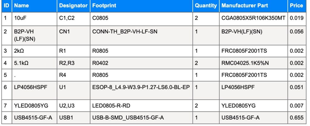
Note: Make sure you buy electronics components from verified online sellers.
Battery Charger Circuit
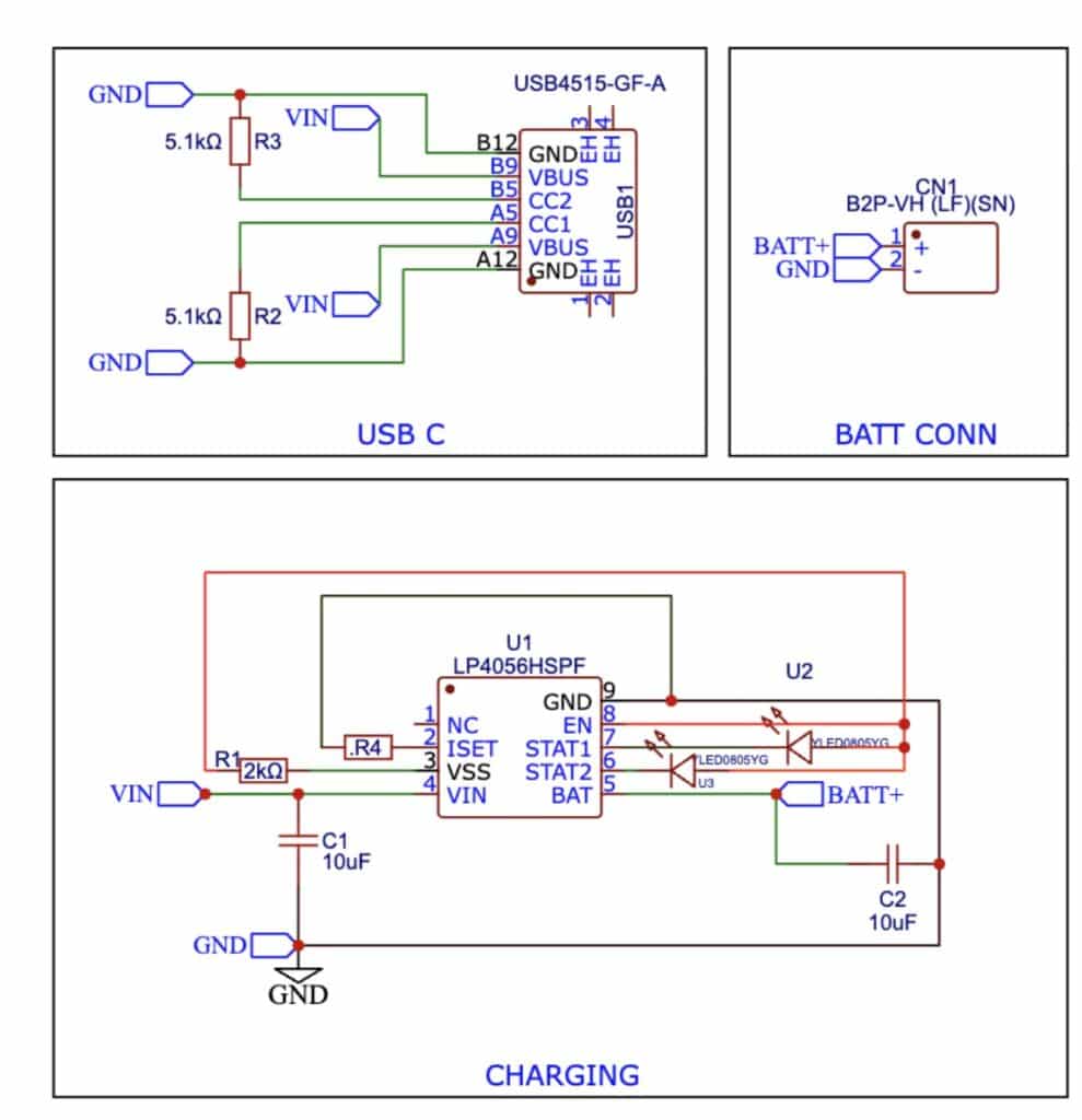
For the circuit design, instead of adding an AC-to-DC converter, we are using a simple USB-C plug that can connect directly to the USB port of your phone, laptop, power bank, or any standard charger/adapter. This provides a convenient 5V (up to around 6V in some cases) DC input without any extra bulk or cost.
In the design, I’ve added a USB-C female connector to accept this 5V–6V DC input. This input is then connected directly to the VIN pin of the LP4056HSPF IC. The IC handles the charging intelligently: it outputs a fixed 4.2V to the battery with automatic constant-current/constant-voltage (CC/CV) mode, manages the current safely, and takes care of everything automatically—no manual intervention needed.
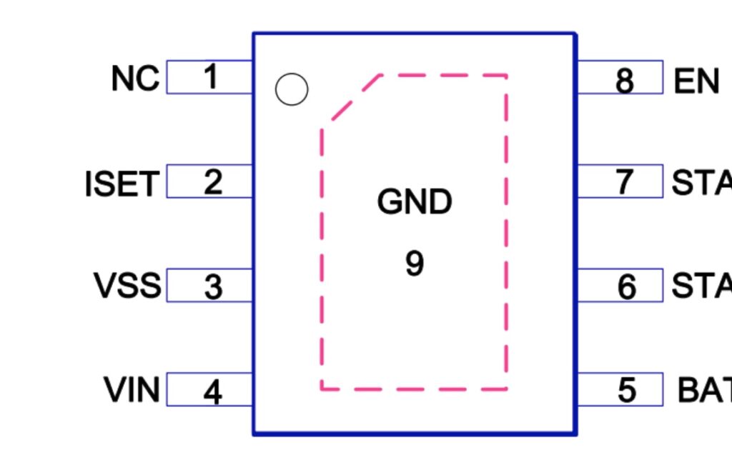
It also features two open-drain status pins for easy monitoring:
- STAT1 (pin 7): Open-drain charge status output. During charging, it’s pulled low by an internal N-channel MOSFET. When charging is complete, it can be pulled high with an external pull-up resistor.
- STAT2 (pin 6): Open-drain charge status output. During charging, it can be pulled high externally; when charging is finished, it’s
For stable operation, only two external capacitors are required: a 10µF capacitor between VIN and GND and another 10µF capacitor between BAT (battery output) and GND. That’s all—no external sense resistor and no blocking diode are needed, thanks to the IC’s built-in MOSFET architecture. Integrated thermal feedback automatically reduces charging current in high-power or high-temperature conditions, preventing overheating.
The charging voltage is fixed at 4.2V, while the charge current is programmed using a single resistor on the PROG/ISET pin (for example, 1.2kΩ ≈ 1A, 2kΩ ≈ 600mA, adjustable as required). Charging automatically terminates when the current falls to one-tenth of the programmed value after reaching the 4.2V float voltage.
When input power is disconnected, the IC enters an ultra-low-power sleep mode, drawing less than 1µA from the battery to minimise drain. Additional features include automatic recharge when battery voltage drops, optional charge-current monitoring, and clear status indication—making the charger efficient, safe, and highly reliable for embedded and IoT applications.
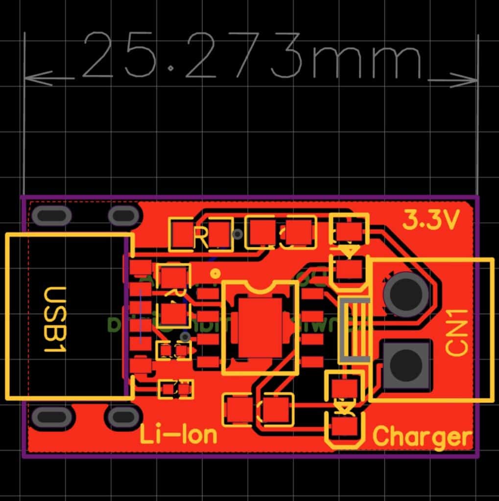
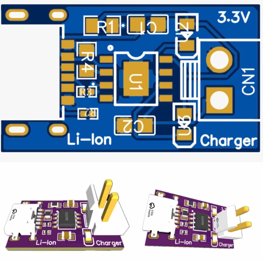
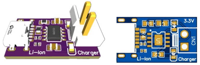
PCB Design
Now, for PCB design, I’ve placed SMT of every component on only one layer. However, I’ve used multilayer tracks to keep the design small, super portable, and easy to use. I’ve used Via multilayer tracks. The complete PCB design I’ve kept under 25 mm, which is smaller than a fingertip.