


The active discharge circuit reduces stored capacitor energy to safer levels while eliminating the continuous power losses associated with conventional discharge methods.
DC-link capacitors with high voltage ratings are widely used in electric vehicles, industrial drives, renewable energy sources, and power converters. These capacitors play an important role in energy storage and power conditioning. However, they can retain high voltages long after the systems are powered down, creating a potential risk of electrical shock for service technicians.
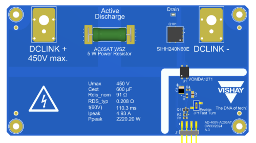
A reference design from Vishay takes care of this situation by providing an active discharge circuit for 800V DC-link systems. The circuit provides a controlled discharge path that rapidly reduces stored energy to a safe level while avoiding the continuous power losses.
One of the design goals here is to discharge a 500 µF DC-link capacitor from 850V to 60V within two seconds. Such rapid discharge requirements align with safety regulations that exist in the automotive industry where stored voltage must be reduced to safe levels after system shutdown
For many years, engineers used permanently attached discharge resistors to lower capacitor voltages after powering down the system. They were relatively simple and easy to implement, but they were always dissipating energy during system operation and lowering efficiency. For high-voltage applications such as traction inverters and EV powertrains this becomes even more important.
Unlike conventional bleed resistors, the active discharge circuit is activated only when needed. The design includes a 1200V SiC MOSFET, a photovoltaic isolated gate driver, and a pulse-resistant discharge resistor. During normal operation, the discharge path remains deactivated. Once a discharge command is received, the MOSFET provides a controlled path for dissipating the energy stored in the DC-link capacitor.
The use of photovoltaic gate drivers is one of the design features as well. This component not only creates galvanic isolation between low voltage electronics of the driver and high voltage part of the circuit, but also doesn’t require any special isolated power source for its functioning.
To support different application requirements, the reference design evaluates multiple resistor technologies. They include wire wound power resistors, carbon film MELF resistors and thick film power resistors.
The reference design also evaluates thermal performance during discharge events. As the resistor and MOSFET have to dissipate huge amounts of energy in relatively short time, the correct thermal evaluation is needed.
For engineers working on electric vehicles, industrial power system, and energy-storage equipment, the reference design offers a practical framework for implementing rapid capacitor discharge while maintaining system efficiency.
Vishay has tested this reference design. It comes with a bill of materials (BOM), schematics, assembly drawing, printed circuit board (PCB) layout, and more. The company’s website has additional data about the reference design. To read more about this reference design, click here.

