


An intuitive EDA tool that transforms breadboard prototypes into schematics and fabrication-ready PCBs. Design, document, and validate electronic circuits before building the actual hardware.
What is Fritzing?
Designing a printed circuit board (PCB) often involves multiple software tools and a steep learning curve, especially for beginners. Fritzing simplifies this process by providing an intuitive electronic design automation (EDA) environment that takes a project from a breadboard prototype to a manufacturable PCB. Developed as an open-source project, the software combines three interconnected design views: Breadboard, Schematic, and PCB, allowing engineers to visualise, document, and manufacture electronic circuits using a single application.
Unlike conventional PCB design software, where engineers typically begin by drawing a schematic, Fritzing starts with a realistic breadboard layout. Every component placement and wiring change is automatically reflected in the schematic and PCB views, helping eliminate inconsistencies during the design process. Once the design is complete, the software generates industry-standard Gerber files that can be sent directly to PCB manufacturers.
Why is Fritzing Useful for Design Engineers?
Fritzing is particularly valuable during the early stages of hardware development. Engineers frequently begin with breadboard prototypes to validate circuit functionality before designing a PCB. The software eliminates the need to redraw the circuit multiple times by automatically converting the prototype into a schematic and PCB layout. Besides speeding up prototyping, Fritzing also serves as an excellent documentation tool. Its realistic component illustrations make circuit diagrams easy to understand for colleagues, customers, and students alike. Engineers developing Arduino-, Raspberry Pi-, ESP32-, or sensor-based embedded systems can rapidly assemble circuits using the extensive built-in parts library instead of creating symbols from scratch.
For whom is this suitable?
- Electronics design engineers developing proof-of-concept hardware
- Embedded system developers working with microcontrollers
- IoT product designers creating rapid prototypes
- Students and educators learning PCB design
- Makers and startups developing low-volume hardware products
- Researchers documenting experimental electronic circuits
While it is capable of producing professional PCB layouts, Fritzing is generally intended for simple to moderately complex boards rather than high-speed multilayer designs. Here is how the editions compare:
| Feature | Self-Compiled Version | Official Download |
| Cost | Free | Paid contribution (one-time donation) |
| Source Code | Available on GitHub | Not required |
| Installation | Requires compiling from source | Ready-to-install binaries |
| Features | Full feature set | Full feature set |
| PCB Design | ✔ | ✔ |
| Breadboard & Schematic Views | ✔ | ✔ |
| Gerber Export | ✔ | ✔ |
| Custom Parts Editor | ✔ | ✔ |
| Software Updates | Manual (recompile newer versions) | Included during the update period after purchase |
| Technical Support | Community forums | Community support + helps fund development |
| Best For | Developers are comfortable building software from source | Engineers, educators, makers, and professionals who want a hassle-free installation |
Key Features
Several features make Fritzing popular among hardware developers:
- Three synchronised workspaces: Breadboard, Schematic, and PCB
- Automatic conversion between design views
- PCB layout and interactive trace routing
- Design Rule Check (DRC) for PCB validation
- Gerber file generation for manufacturing
- Extensive library of Arduino, Raspberry Pi, ESP32, Adafruit, and common electronic components
- Custom component creation using the integrated Parts Editor
- High-quality SVG graphics for project documentation
- Cross-platform support for Windows, Linux, and macOS
How Fritzing Works
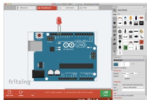
1. Create the Circuit Prototype: The design process starts in Breadboard View, where engineers assemble the circuit using a virtual breadboard. Components such as resistors, capacitors, ICs, Arduino and ESP32 boards, sensors, connectors, and displays can be dragged from the Parts Library and wired together just as they would be on a physical prototype. This visual approach allows engineers to quickly validate circuit connections before committing to a PCB design.
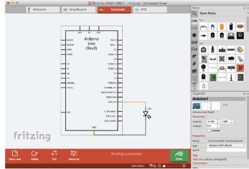
2. Generate the Schematic Automatically: As the breadboard circuit is created, Fritzing simultaneously generates the corresponding schematic diagram. Since all views remain synchronised, any modification made to the breadboard is automatically reflected in the schematic and vice versa. Engineers can reorganise the schematic for better readability while ensuring that all electrical connections remain intact.
3. Design the Printed Circuit Board (PCB): After verifying the schematic, users switch to the PCB View. Here, components are arranged on the board outline, and electrical connections are routed as copper traces. Fritzing supports both manual routing, which gives engineers greater control over the PCB layout, and auto-routing for simpler designs. Designers can also define board dimensions, place mounting holes, add silkscreen labels, and optimise component placement before fabrication.
4. Check the Design for Errors: Before sending the board for manufacturing, Fritzing performs a Design Rule Check (DRC) to detect common PCB design issues such as overlapping traces, insufficient spacing, or missing connections. Identifying these problems early helps engineers reduce design iterations and avoid costly manufacturing errors.
5. Export Manufacturing Files: Once the PCB design is complete and validated, Fritzing generates Gerber (RS-274X) files, which are accepted by most PCB fabrication houses. The software can also export Bills of Materials (BOM), pick-and-place information, SVG graphics, PDFs, and high-resolution images for manufacturing, assembly, and project documentation.
In essence, Fritzing streamlines the entire hardware design workflow by taking engineers from a virtual breadboard prototype to a fabrication-ready PCB within a single application. By automatically synchronising the breadboard, schematic, and PCB layouts, it minimises manual effort, reduces design errors, and speeds up the transition from concept to physical hardware.
What’s New in Fritzing 1.0.7?
The latest version, Fritzing 1.0.7, was released in April 2026, with a strong emphasis on performance, stability, and compatibility with modern hardware rather than introducing entirely new workflows. One of the biggest improvements is native support for Apple Silicon processors, allowing the software to run directly on M-series Macs without Rosetta emulation. The application has also been upgraded to the Qt 6.8.3 framework, resulting in smoother graphics rendering, improved responsiveness, and enhanced platform support. As per one design engineer, “It makes moving from a breadboard prototype to a PCB incredibly straightforward.”The recent updates have made the software much faster and more stable than earlier versions.”
Another significant enhancement is the addition of nearly 300 new components to the Adafruit Parts Library, giving engineers access to a wider range of readily available development modules. Faster startup times, optimised SVG rendering, and improved memory management make the software noticeably more responsive, particularly when working with larger projects.
Recent releases have also introduced several practical improvements. Version 1.0.6 enabled hardware acceleration by default, improved PCB editing, enhanced Gerber export, and added a dedicated Adafruit Parts Bin. Version 1.0.5 brought Windows ARM support, Arduino CLI integration, improved font rendering, and experimental graphics acceleration. Together, these updates demonstrate that the development team is focused on making Fritzing faster, more stable, and better suited for modern hardware development workflows.
How to Get Started
Getting started with Fritzing is straightforward, even for first-time PCB designers. The software is ideal for engineers who have already built a circuit on a breadboard and want to convert it into a schematic and PCB layout without learning a complex EDA workflow. You can download the latest version from the official Fritzing website. While the source code is freely available, the official pre-built installers require a small contribution that supports ongoing development.
Official Download: https://fritzing.org/download
Follow these steps to create your first PCB design:
1. Download and Install
Visit the official Fritzing download page.
Choose your operating system (Windows, macOS, or Linux).
Download the installer and complete the installation.
Launch Fritzing after installation.
2. Create a New Project
Open Fritzing and select File → New.The project opens in the Breadboard View, where you can begin assembling your circuit.Drag and drop components from the Parts Library, including Arduino boards, Raspberry Pi modules, ESP32 boards, sensors, LEDs, resistors, and connectors.Connect components using virtual wires, just as you would on a physical breadboard.
3. Verify the Schematic
Switch to the Schematic View. Fritzing automatically generates the circuit schematic from your breadboard design. Rearrange components if needed to improve readability and verify all electrical connections.
4. Design the PCB
Open the PCB View. Define the board outline and dimensions. Position components on the PCB. Route copper traces manually or use the auto-routing feature for simple designs. Run the built-in Design Rule Check (DRC) to identify spacing or routing issues before fabrication.
5. Export Manufacturing Files
Once the PCB passes all checks, select File → Export → For Production → Extended Gerber (RS-274X). Fritzing generates the complete set of Gerber files required by most PCB fabrication services. You can also export the Bill of Materials (BOM), PCB images, PDFs, and SVG files for documentation. Within a few steps, engineers can transform a working breadboard prototype into a professionally documented, fabrication-ready PCB. By combining circuit visualisation, schematic capture, PCB layout, and manufacturing file generation in a single application, Fritzing significantly reduces the time required to move from concept to hardware, making it an excellent choice for rapid prototyping, embedded system development, and electronics education.
Licensing and Availability
Fritzing remains an open-source project. Engineers can download the source code free of charge and compile it themselves. The official pre-built installers available from the Fritzing website require a modest contribution that supports ongoing development. Unlike many commercial EDA tools, there is no restricted “free” edition; the official download includes the complete feature set, including PCB design, Gerber export, custom part creation, and project documentation tools. This community-supported funding model has enabled regular software updates and continuous improvements over the past few years, ensuring that Fritzing remains a practical and accessible PCB design platform for engineers, educators, and makers alike.