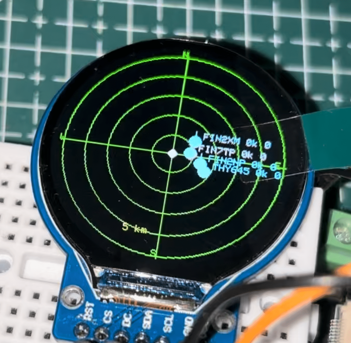
The purpose of this Flight Radar is to track Unmanned Aerial Vehicles (UAVs), drones, and flights flying overhead. It is not actually connected to any physical radar. Instead, it uses platforms where radar systems around the world feed data about tracked flights, UAVs, and drones. The device connects to these platforms and displays the collected data.
The design connects to Application Programming Interfaces (APIs) and gathers data within a set radius around a configured location, displaying information about what is flying over the selected area. The location can be configured to receive real-time data about flights, drones, and UAVs operating within the selected range.
Multiple APIs can be used to connect to flight data platforms. However, for applications that require a real radar system to intercept actual messages and signals transmitted by UAVs, flight, and drone transponders, an RTL-SDR flight radar module and a radar antenna can be used. Such a setup can also act as a data feeder to the network, allowing flight data to be monitored according to the receiver’s location and shared with the network. This method is explained in another design here: Raspberry Pi Flight Tracker.
In the current design, the ESP chip connects to the OpenSky and OpenData ADS-B APIs to collect real-time flight data within the selected area and displays details such as the callsign, speed, and altitude of each flight.
Bill of Material
In the design, we will use the ESP32-based IndusBoard Coin to keep the design super small. Otherwise, you can use any ESP32-based development board; the design remains almost the same for all ESP chips. Along with the ESP chip, we will use a display. Here we have chosen the round display that is almost the same size as the IndusBoard Coin, super small, only 3 cm.
| Component | Description | Quantity |
| IndusBoard Coin | WIFi MCU board | 1 |
| GC9A01 LCD display | SPI display | 1 |
| USB C cable | For flashing firmware | 1 |
| 3.3V NimH or LiPo Battery / Power Supply | 3.3V 1A Power Supply | 1 |
ESP32 Flight Tracker Circuit
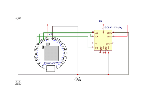
The display is connected to the ESP chip according to the circuit diagram. (Refer to Fig. 2)
Code for Flight Tracker
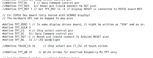
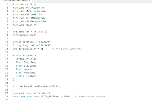
For driving the display, the TFT_eSPI library needs to be installed. The display type, board, and pin connections must then be configured.
Go to Libraries → TFT_eSPI → User_Setup file.
In the TFT_eSPI library, the display driver needs to be configured first. All other display models should be commented out, while the GC9A01 display should be uncommented. The pins used to connect the display are then configured before saving the file.
The firmware first checks the configured SSID and password and attempts to connect to the specified Wi-Fi network. If the connection fails, the device starts a Wi-Fi hotspot and waits for the Wi-Fi credentials to be configured.
The same portal webpage also allows configuration of the timezone, the location from which flights are to be scanned, and the Wi-Fi SSID and password. Once the configuration is complete, the settings are saved and the device restarts.
During the next power-up, the device starts with the saved location and Wi-Fi network configuration. After connecting to the Wi-Fi network, it calls two APIs to fetch flight data within the configured radius. The first source is OpenData ADS-B, followed by the OpenSky API.
After the data is fetched, the display shows the flight information along with the distance from the configured location. Data obtained from each API is displayed in different colours for easier identification. Information such as the flight name, speed, and altitude is updated in real time.
The scan radius can be configured through the same access-point mode, with options ranging from 5 km to 30 km. Larger ranges are also possible, although displaying data from a wider area may make the screen crowded.
Testing
The device is powered using a 3.3V supply or LiPo battery. It then creates its own Wi-Fi hotspot. After connecting to the hotspot, the configuration page opens automatically (Refer Fig. 5).
The configuration page allows the Wi-Fi SSID and password, latitude and longitude of the location, scan radius (5 km, 10 km, 15 km, or 30 km), and timezone to be configured.
After all the settings are configured, clicking Save stores the configuration and restarts the device. It then automatically connects to the configured Wi-Fi network and starts displaying flight data in real time (Refer Fig. 6).