



Mesh swarm robots offer a practical approach to collaborative robotics, with multiple autonomous units communicating, sharing information, and coordinating their actions to perform complex tasks. These systems are particularly suited to applications that require distributed sensing and decision-making, including environmental monitoring, area surveys, gas-leak detection, and search-and-rescue operations.
In this system, each robot in the mesh swarm is equipped with an AMG8833 thermal sensor, N20 motors, motor drivers, and an IndusBoard that integrates multiple onboard sensors. Additional end-effectors, such as claws, can also be fitted as required. The robots operate through a mesh network supporting multiple master, receiver, and bridge nodes. A master node receives high-level commands from a Wi-Fi access point or bridge and distributes tasks among the individual robots, enabling coordinated thermal surveys and analysis.
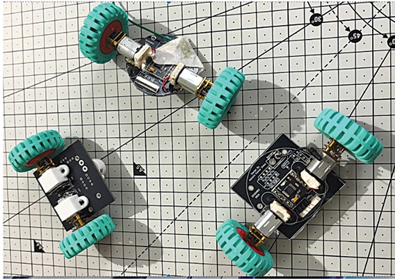
As the robots move, they continuously exchange position data and sensor readings with one another and report the collected information to the master node. The master aggregates and analyses the data, particularly the thermal readings, and generates alerts when a robot detects a thermal anomaly, fire source, or high-temperature signature that may indicate a gas leak. This coordinated mesh architecture helps improve the speed, coverage, and reliability of thermal inspection and emergency-response missions. Fig. 1 shows the author’s prototype. The components required to build this system are listed in the Bill of Materials table.
| Bill of Materials | |||
| Name | Designator | Description | Qty |
| Screw terminal | CONN1 | 2-pin battery connector | 4 |
| XW0520012-240R-001 | FPC1 | FPC SMD 24-pin, 0.50mm pitch connector | 4 |
| N20 motor | M1, M2 | N20 DC motor, 3V-7V DC | 8 |
| AMG8833 module | S1 | AMG8833 thermal sensor module | 2 |
| IndusBoard V2 | IC1 | IndusBoard Coin V2 | 3 |
| DRV8833 module | IC2 | DRV8833 dual motor driver module | 8 |
| Soldering jumper, 2-pin | — | 2-pin soldering jumper | 8 |
| Buzzer | PB1 | Piezo buzzer | 4 |
Circuit and working
The master and swarm robot nodes use essentially the same circuit, except that the AMG8833 thermal sensor is required only on the swarm robots. The DRV8833 controls the two DC gear motors, while the IndusBoard V2 connects to the main PCB through an FPC connector, with other required sensors and interfaces integrated on the board.
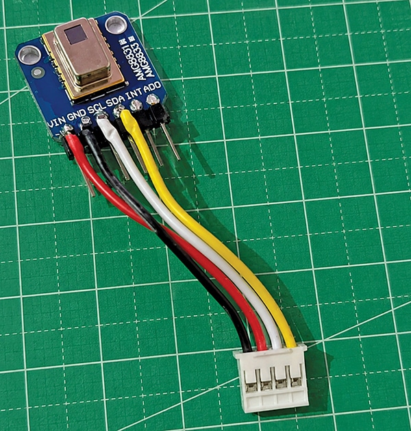
Fig. 2 shows the two-wheel differential-drive controller based on the IndusBoard V2, comprising the DRV8833 motor driver, two N20 geared motors, the AMG8833 thermal sensor, and pushbutton PB1. The IndusBoard controls the DRV8833 through GPIO pins and communicates with the AMG8833 via I²C. PB1, connected between IO33 and ground, is used for starting or selecting functions. Fig. 3 shows the AMG8833 module and connector.
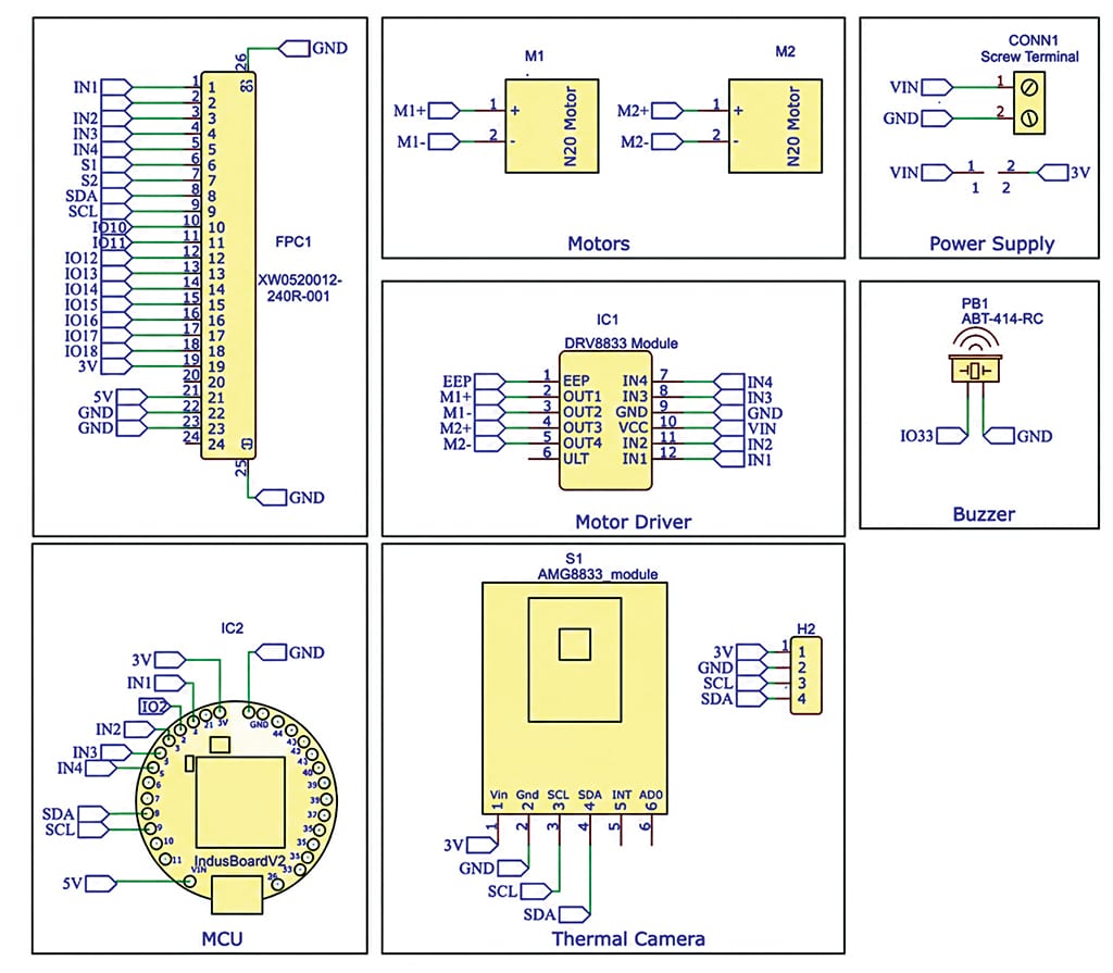
The DRV8833 drives motor M1 through OUT1-OUT2 and M2 through OUT3-OUT4. Independent motor control enables forward, reverse, and turning movements. The motor supply is connected through CONN1, with VIN supplying the driver and GND providing a common ground.
The AMG8833 communicates with the IndusBoard V2 via I²C and provides temperature data from its 8×8 (64-element) array. The IndusBoard processes this data to detect heat sources and determine their direction, then generates IN1-IN4 control signals for the DRV8833. The driver converts these signals into motor currents to control the direction and movement of M1 and M2.
Overall, the signal and control flow is AMG8833→I²C→IndusBoard V2→IN1-IN4→DRV8833→M1/M2. The AMG8833 provides thermal data, the IndusBoard V2 processes the data and controls movement, and the DRV8833 drives the two motors. The same architecture is used for the master and swarm robots, with the thermal sensor added only to the swarm nodes. This compact design supports coordinated autonomous differential-drive robots.
Software
The system was developed using the Arduino IDE. Two separate programs were developed: one for the master swarm robot and another for the swarm thermal sensor robot nodes. The painlessMesh library establishes Wi-Fi-based multi-hop mesh communication between the robots, while the ArduinoJson library is used for structured data exchange.
Master swarm robot node
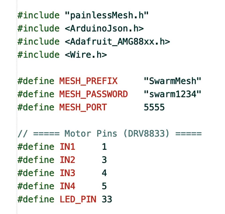
The master node program starts by defining the mesh credentials and required GPIO pins, initialises the mesh network, and configures callbacks to receive data from the child nodes.
When a message is received, the master parses the JSON packet containing temperature data, alarm status, RSSI value, and the complete 64-point thermal array. If an alarm condition is detected based on the preset temperature threshold, the master activates the buzzer. It also hosts a web server through which users can view live thermal heatmaps received from the swarm robots.
Swarm thermal sensor robot nodes
The swarm thermal sensor robot node program configures the motor-driver GPIO pins and assigns a unique name or identity to each robot. It initialises the AMG8833 8×8 thermal sensor and periodically reads its 64 temperature values. The collected thermal data and robot status information are formatted into a JSON packet and transmitted through the mesh network to the master node.
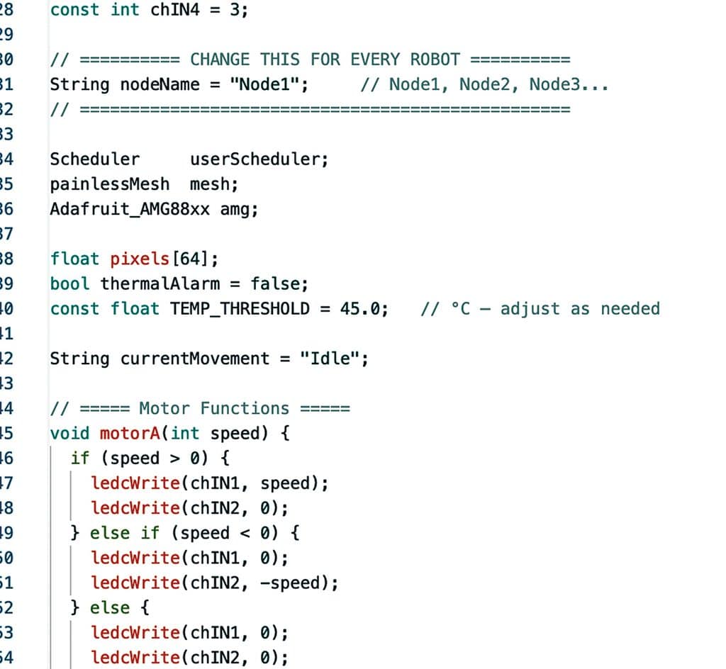
Before uploading the programs, the same MESH_PREFIX and MESH_PASSWORD must be configured on the master and all child nodes. Each child robot must have a unique nodeName, and the correct motor-driver GPIO pins must be defined. The TEMP_THRESHOLD should be adjusted according to the required thermal alarm level, while the appropriate GPIO pins for the buzzer and LED must be selected on the master node. The correct I²C pins for the AMG8833 thermal sensor should also be configured on the thermal sensor nodes. Fig. 5 shows the swarm thermal sensor node configuration, including the node name and identity.
Construction and testing
First, the master code is uploaded to the master node, while the swarm robot code is uploaded to each child node. After uploading the programs, the circuit is assembled according to the circuit diagram. Before assembling the circuit, Fig. 1 should be referred to for the prototype, Fig. 2 for the circuit diagram, and Fig. 3 for the thermal sensor connection to identify the required connections and component placement.
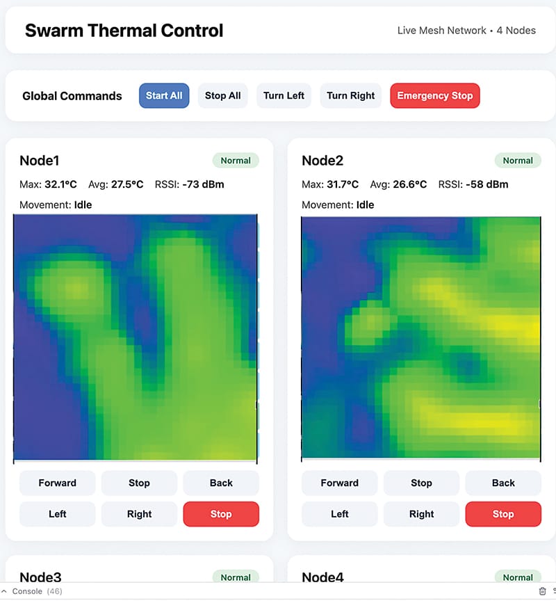
After completing the assembly, each robot may be powered on and tested individually to verify the motor connections, thermal sensor operation, and wireless communication. The AMG8833 thermal sensor should be checked for proper thermal-image generation, and the temperature data is transmitted through the mesh network to the monitoring interface. The robot movement commands, including Forward, Reverse, Left, Right, and Stop, are tested to ensure proper motor operation. The global commands—Start All, Stop All, Turn Left, Turn Right, and Emergency Stop—are also tested through the central control interface. During testing, the dashboard should successfully display the thermal images, maximum and average temperature values, RSSI, and movement status of the connected nodes. Fig. 6 shows the Swarm thermal control dashboard.
The complete swarm system should be subsequently tested with multiple robots operating simultaneously. In the final test, four swarm nodes may be connected through the mesh network and monitored from the central dashboard. Each node transmits its thermal data and wireless signal strength, while individual movement commands are issued through the interface. The dashboard displays the thermal images and node status, and the motor control and emergency-stop functions as intended.
Ashwini Kumar Sinha, an IoT and AI enthusiast, is Tech Journalist at EFY.