


This soccer robot project can effortlessly move forward, reverse, and navigate in multiple directions, including forward-left, forward-right, reverse-left, and reverse-right, all controlled via an Android phone. The speed of its movement is controlled by the angle of rotation of the phone. The robot also kicks a ball when the phone is shaken.
Soccer Robot Circuit
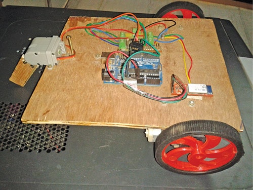
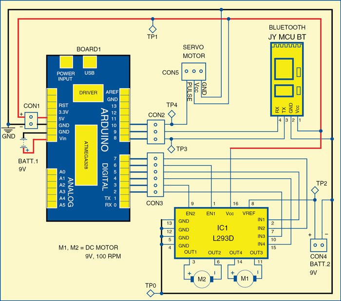
Shown below is the circuit of the soccer robot. The circuit is built around an Arduino UNO board (BOARD1), servo motor (connected at CON5), Bluetooth module JY MCU BT, motor driver L293D (IC1) and two DC motors (M1 and M2).
The circuit uses two 9V batteries; one for the Arduino board (BOARD1) and the other for DC motors. The 5V regulated supply for the rest of the circuit is provided by the Arduino board itself. LED on BOARD1 indicates the presence of a power supply.

All new smartphones contain an accelerometer sensor. A phone with an accelerometer can detect the angle it is being held. It can also detect rotation and motion gestures such as swinging, shaking and flicking.
The accelerometer can detect whether the phone is upright or sideways, and automatically rotate the graphics on the screen accordingly.
Another common use is in controlling games and other applications (such as music players) by moving or shaking the phone.
When the phone is rotated in different directions, the x, y, and z values of the accelerometer sensor change. The Android app for this project sends these x, y, and z values to the robot via Bluetooth.
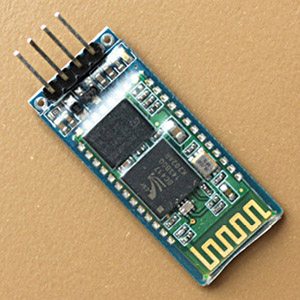
Bluetooth Module
The Bluetooth module used in this project is JY MCU BT, which can be connected to any device via a built-in UART interface. It can communicate with other Bluetooth-enabled devices such as mobile phones, handheld computers and laptops. The module runs on a 3.6V to 6V supply.
Servo Motor
A servo motor is used for kicking the ball in this project. Servos are extremely useful in robotics. The motors are small but extremely powerful for their size. A servo motor mainly comprises a DC motor, gear system, position sensor (which is generally a potentiometer) and control electronics as shown in the image below.
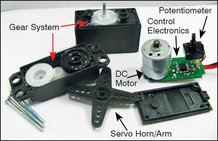
The DC motor is connected with a gear mechanism which provides feedback to a position sensor. The potentiometer allows the control circuitry to monitor the current angle of the servo motor. If the shaft is at the correct angle, the motor shuts off.
If the circuit finds that the angle is incorrect, it keeps the motor on until the angle is corrected. A normal servo is used to control an angular motion up to 180 degrees. servos are incapable of turning further due to a mechanical stop built on the main output gear.
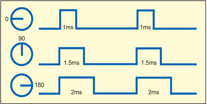
The control wire is used to communicate the angle. The angle is determined by the duration of a pulse that is applied to the control wire. This is called pulse-coded modulation. The servo expects to see a pulse every 20 milliseconds. The length of the pulse will determine how far the motor turns.
For example, a 1.5-millisecond pulse could turn the motor to a 90-degree position (often called the neutral position).
If the pulse is shorter than 1.5 milliseconds, the motor would turn less.
If the pulse is longer than 1.5 milliseconds, the shaft would turn closer to 180 degrees as shown above.
Servo motor arm is connected to a metal or wooden piece so that the servo arm acts as a leg to kick the ball.
Arduino UNO Board
Arduino is an open-source electronics prototyping platform based on flexible, easy-to-use hardware and software. It is intended for artists, designers, hobbyists and anyone interested in creating interactive objects or environments.
Arduino UNO is a board based on the ATmega328 microcontroller. It consists of 14 digital input/output pins, six analogue inputs, a USB connection for programming the on-board microcontroller, a power jack, an in-circuit serial programming (ICSP) header and a reset button.
The board is operated with a 16MHz crystal oscillator and contains everything needed to support the microcontroller.
It is very easy to use as the user simply needs to connect it to a computer with a USB cable, or power it with an AC-to-DC adapter or battery, to get it started. The microcontroller on the board is programmed using Arduino programming language and Arduino development environment.
Pins 8 and 9 of BOARD1 are connected to pins Tx and Rx of the Bluetooth module, respectively. Pin 10 is connected to the PULSE pin of the servo motor to control the angle of movement. Pins 2 through 7 of BOARD1 are output pins that are connected to IC1 for controlling the motors.
Pins 2, 3 and 4 of BOARD1 are connected to IN3, EN2 and IN4 of IC1 to control motor M1, and pins 5, 6 and 7 are connected to IN1, EN1 and IN2 of IC1 to control motor M2. EN1 and EN2 are used to control the speeds of the motors.
The app sends the sensed data from an accelerometer of the phone to the robot via Bluetooth. Data transmitted by the phone is received by the Bluetooth module on the robot. The received data is fed to pin 8 of BOARD1. The microcontroller on BOARD1 processes the received data and drives the motors accordingly.
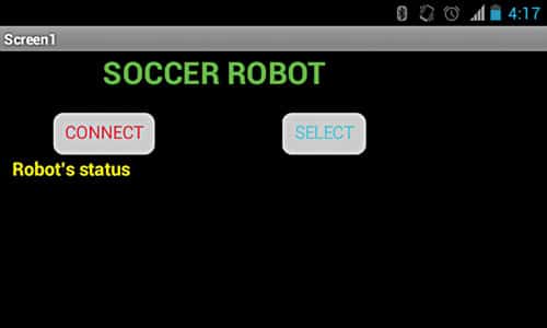
The robot also sends back the status. In the app, you can see a label named ‘Robot’s status’ below which you can see the direction in which the robot is moving and also the kick status.
Arduino Code for Soccer Robot
The code for the soccer robot is written in Arduino programming language. The Arduino UNO is programmed using Arduino IDE software.
Atmega328 on Arduino UNO comes with a boot loader that allows you to upload new code to it without the use of an external hardware programmer. It communicates using the STK500 protocol.
You can also bypass the boot loader and program the microcontroller through the ICSP header, but using boot loader programming is quick and easy.
Select the correct board from the ‘Tools→Board’ menu in Arduino IDE and burn the program (sketch) through a standard USB port in the computer.
Change the kick and initial position (in degrees) of the soccer robot’s leg in the source program corresponding to your mechanical arrangement of the leg in the robot as shown below:
Int kick = 50
Int neutral = 170
The procedure for installing the Android app on the phone is as follows:
- Download the app SoccerRobot.apk and copy it to your Android smartphone or tablet.
- Run the file and it will ask you ‘complete action using,’ click on ‘package installer’ and then click ‘install.’
Please note that you have to also change the baud rate of the Bluetooth module on the robot to 57600 using the AT command if it is not set like that already.
Download Source Code: click here
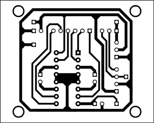
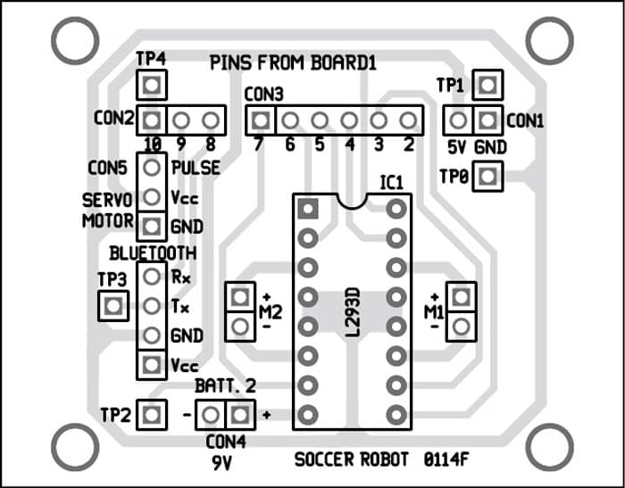
PCB Design
A single-side PCB for the soccer robot and its component layout is shown below. Assemble the circuit on the recommended PCB to save time and minimise assembly errors. Use IC base for motor driver IC1.
Download the PCB and Component Layout PDFs: click here
Testing Robo Soccer Project
Follow the steps below to get the robot running for the first time:
- Switch the power supply to the robot by connecting the batteries.
- Pair the Bluetooth module with an Android phone. While pairing, it will ask you for the password; type ‘1234’ which is the default password of Bluetooth module.
- Run the already installed app on the phone.
- Tap ‘SELECT’ (ensuring Bluetooth is enabled), then choose the Bluetooth module from the list of scanned devices and press ‘CONNECT.’ It will take 5-10 seconds to connect. After connecting, it will notify you that Bluetooth is connected. Now it is time to play soccer through your phone.
- You can control the robot by rotating the phone; ‘Forward,’ ‘Backward,’ ‘Left,’ ‘Right’ and ‘Stop.’
- Kick the ball by shaking the phone.
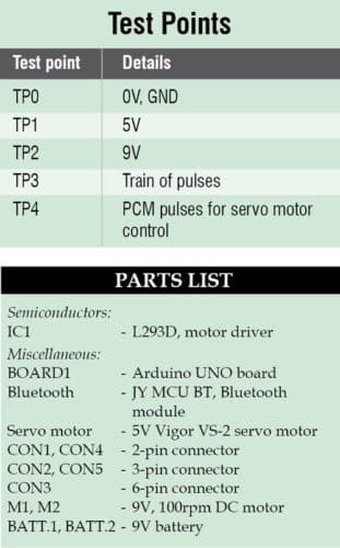
To test the circuit for proper functioning, verify the correct 5V supply for the circuit at TP1 with respect to TP0. Also, check the 9V supply for the motors at TP2. Transmitted data by Bluetooth can be observed at TP3. The controlling pulses for the servo motor can be seen at TP4.
This article is a part of the Top 15+ Microcontroller Projects. If you want to check more projects based on microcontrollers, can go through this article.
The article was first published in January 2015 and updated recently in 2024.
What will be the code for this??
The source code is present within the article.
help! the servo motor doesn’t work
the app doesn’t work well
somebody can help us, we’re doing the soccerrobot as a project at school but, when we conect it by bluetooth we our phone it dosen’t work. Please answer us.