


The design has many connection options, timing features, and power monitoring. It is useful for networking, industrial systems, and embedded devices.
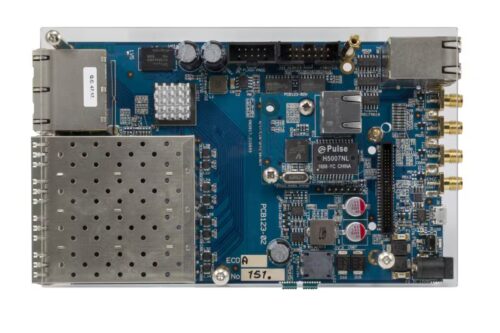
The VSC7514EV reference board from Microchip demonstrates the VSC7514 Ethernet switch device. It provides multiple connectivity options and management capabilities for Ethernet networking.
The reference design is suitable for networking equipment manufacturers, embedded system developers, telecom and industrial automation engineers, R&D teams, and educational institutions. It provides a platform for designing Ethernet switches, integrating Ethernet switching into custom hardware, and developing precision timing and synchronization solutions using PTP and Sync-E. Engineers can use it to test and evaluate the VSC7514 switch before final product integration, while researchers and students can study Ethernet networking, embedded systems, and communication protocols.

The board includes four 10/100/1000BASE-T Ethernet copper ports with integrated PHYs and eight 100M/1Gbit/s Ethernet SFP ports connected to the VSC7514 through SERDES. Two of the SFP ports are dual-media ports linked to two of the copper ports, and three of the SFP ports support 2.5Gbit/s speeds. Additionally, there is an optional 10/100/1000BASE-T (RJ45) Ethernet port using a VSC8221 PHY connected to the VSC7514 via SGMII.
By default, the design is managed by an embedded MIPS CPU system with onboard DDR3, NOR, and NAND Flash devices. However, an external master CPU system can optionally connect to the VSC7514 in slave mode through PCIe, SPI, or the NPI port, using VRAP for inband management.
For synchronization applications, the board features four SMAs and an RS422 interface for PTP and Sync-E. It also supports various Sync-E modules through the Sync-E feature connector. A serial port, implemented through an onboard serial-to-USB converter, allows access to the command line interface (CLI) software debugger by connecting the board to a PC via a USB cable.
Additional hardware features include a reset button with a one-shot reset function, enabling firmware to detect the button state after a reset for functions like “reset to factory defaults.” The board also has a system status LED, port status LEDs, and a 12V DC power input socket.
The MIC8114 is an affordable microprocessor supervisory circuit used in the reference design to monitor power supply levels in microprocessor-based systems. It triggers a reset signal if the supply voltage drops below a defined threshold or if the /MR pin is driven low. With an active-low /RESET output, it ensures the reset signal remains asserted for at least 790 ms after VCC exceeds the threshold. The MIC8114 is housed in a compact 4-lead SOT-143 package.
Microchip has tested this reference design. It comes with a bill of materials (BOM), schematics, assembly drawing, printed circuit board (PCB) layout, and more. The company’s website has additional data about the reference design. To read more about this reference design, click here.
