


This tutorial explains how to build an AI-enabled smart home automation using ESP RainMaker. The system supports lights, fans, relays, sensors, RGB LEDs, OTA firmware updates, QR provisioning, and voice control via Alexa, Google Assistant, and Apple Home, all managed from a single app and dashboard.
AI smart speakers and AI-enabled home automation devices are widely adopted and continue to see strong demand. However, achieving seamless integration with a high level of customisation remains challenging, particularly when adding sensors, lights, switches, relay actuators, fans, and bulbs to meet specific requirements.
In practice, smart bulbs, switches, and sensors are typically sold as standalone devices. No single customisable platform enables sensors, bulbs, fans, actuators, and displays to operate together as a unified, centralised system. As a result, multiple independent devices must be connected and integrated, making automation management complex.
This challenge is further intensified by the reliance on multiple mobile applications and device-specific notifications, with no consolidated control interface available.
Designing a custom IoT controller introduces additional complexity, particularly when integration with AI smart speakers such as Alexa, Apple Home, or Google Assistant is required. Native integration options are limited and often rely on third-party, API-based solutions. Seamless provisioning, device reset, and over-the-air firmware management are also difficult to implement reliably and frequently remain at a prototype stage rather than being suitable for production deployment.
This system addresses these challenges by using the IndusBoard Coin and leveraging its compatibility with the RainMaker platform. RainMaker enables a production-ready system design with wireless firmware management, device monitoring, and provisioning. It allows Wi-Fi credentials to be configured wirelessly, in a manner aligned with commercially available smart home devices.
The approach delivers a complete manufacturer-to-client endpoint solution while enabling seamless integration with Apple Home, Google Assistant, and Alexa for smart assistant-based automation. The IndusBoard Coin provides more than 30 I/O pins, offering the flexibility to add displays, sensors, bulbs, relays, and actuators, all controlled through a single system.
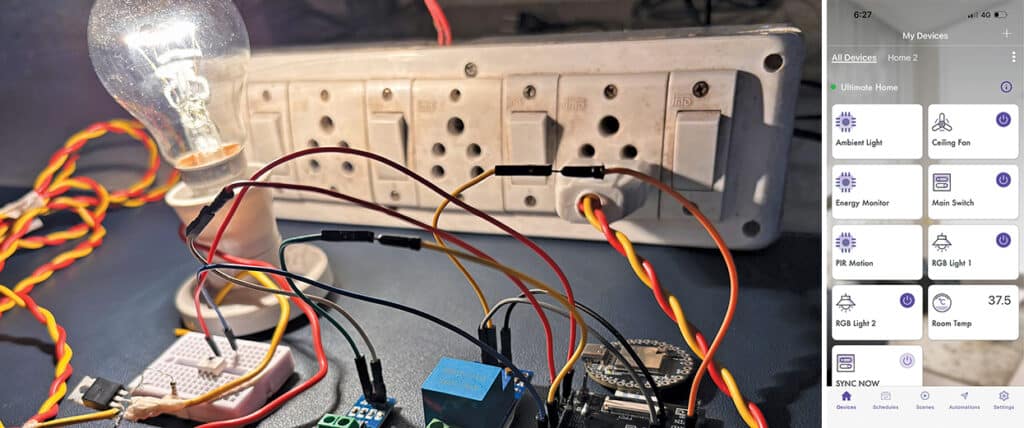
Its inbuilt touch-sensing I/O supports touch-based switching, resulting in an AI assistant-enabled home automation system that is end-user ready, suitable for production, and fully customisable. Fig. 1 shows the prototype, and the required components are listed in the Bill of Materials table.
POC Video Tutorial
| Bill Of Materials | ||
| Name | Designator | Quantity |
| IndusBoard Coin | MOD1 | 1 |
| Relay module | RL1-RL3 | 3 |
| Fan speed controller module (F1) | F1 | 1 |
| Neo pixel LED light | L1, L2 | 2 |
| 3.3V AC-DC power module | MOD2 | 1 |
Programming ESP RainMaker Home Automation System
ESP RainMaker is used as the software platform. The IndusBoard Coin runs custom RainMaker firmware, enabling devices within the system to be controlled, monitored, and updated through the RainMaker app. The system can be seamlessly linked to Alexa, Google Assistant, and Apple Home, enabling control through voice assistants.
The platform also supports remote monitoring, firmware updates, and sensor-based automation, while remaining fully customisable. Prebuilt firmware for light, fan, and switch control is available on the RainMaker platform; however, the platform focuses on a fully customisable implementation, with custom firmware developed in the Arduino IDE.
In the firmware design, the RainMaker library is used. As addressable LEDs are used for light colour and brightness control, an additional library, such as FastLED, is required to ensure efficient LED management.
Although a human–machine interface with a display-based interface can be implemented, this system focuses on a simplified design without a display. Instead, the touch I/O pins are used as touch switches. The system can be controlled via Alexa or Google Assistant voice commands, the mobile app, or the touch switches.
The board provides more than ten touch and proximity (contactless) I/O pins. A touch threshold is defined in the code to set the sensitivity of the touch inputs.
The provisioning name and proof of possession (PoP) can also be configured. These credentials, either unique or user-defined, are shared with the client to connect the device to a network and account, following a setup process similar to that used by commercially available smart bulbs and controllers. Fig. 2 shows a code snippet that configures the RainMaker device.
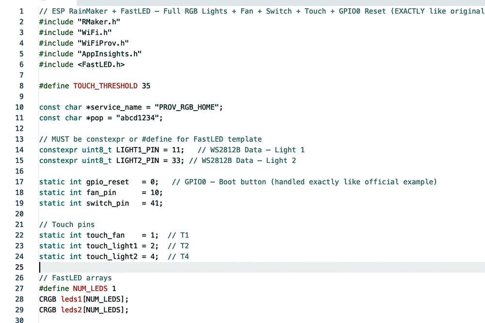
Next, the required lights, relays, and sensors are added, and their respective pins are defined. In this implementation, the controller includes a motion sensor, two lights, one fan, one switch, and an illuminance sensor. Touch pins 1, 3, 4, and 5 are assigned to enable touch-based on or off control for all devices.
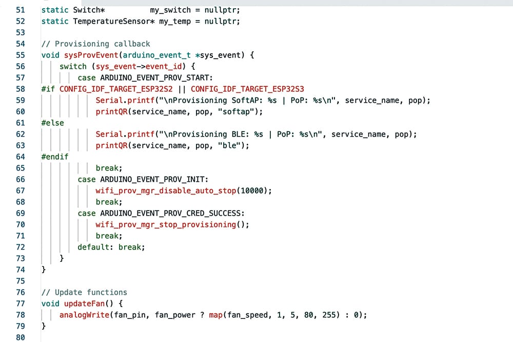
A provisioning function is implemented to generate a QR code that enables the device to be added to the app and configured with Wi-Fi credentials. A reset function is also implemented using the boot button on pin 0 of the board. Pressing and holding the boot button for three seconds resets the Wi-Fi configuration, while holding it for ten seconds restores the device to factory settings and restarts the provisioning process. Fig. 3 shows the code snippet illustrating the provisioning function.
Circuit Diagram
Fig. 4 shows the system’s circuit diagram. It is built around IndusBoard Coin (MOD1), three relay modules (RL1-RL3), two NeoPixel LED displays (L1, L3), and a few additional components.
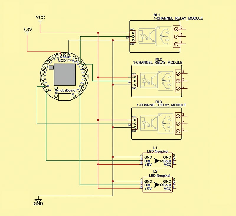
The three relay modules are used for fan control. If fan speed control is required, the code includes an option for that. The relay can be replaced with a fan speed regulator module that accepts a PWM input signal to control the fan. Alternatively, a custom speed regulator or solid-state relay (SSR) can be designed based on system requirements.
The IndusBoard can power the 3.3V AC-to-DC adaptor. The light and relay can be powered using the Vcc (5V DC). For RGB light PCB modules consuming 9-10 watts, power can be supplied using a 220V AC line. The data pin connects to the I/O pin of the board.
Provisioning the Device
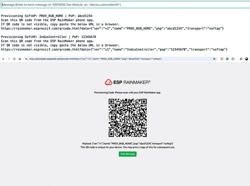
First, upload the source code to the IndusBoard. After the upload is complete, open the serial monitor. A link for generating the provisioning QR code will be displayed. Copy this link and paste it into a web browser to generate the QR code. Save and download the QR code.
For production deployment, print the QR code on the user manual and packaging for the end user. The device can then be provisioned easily by scanning the QR code. Fig. 5 shows the device QR code generated for provisioning.
Download the RainMaker app from the App Store or Play Store and sign in using an email account or iCloud account. In the app, select the plus icon at the top. The app will prompt you to scan a QR code. Scan the previously saved QR code.
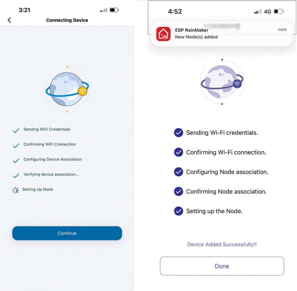
After the app connects to the device’s Wi-Fi network, select the home Wi-Fi network and enter the password. The app will handle configuration, send Wi-Fi credentials, connect the device, and add it to the RainMaker platform. A notification confirms successful addition. Fig. 6 shows the app provisioning the device.
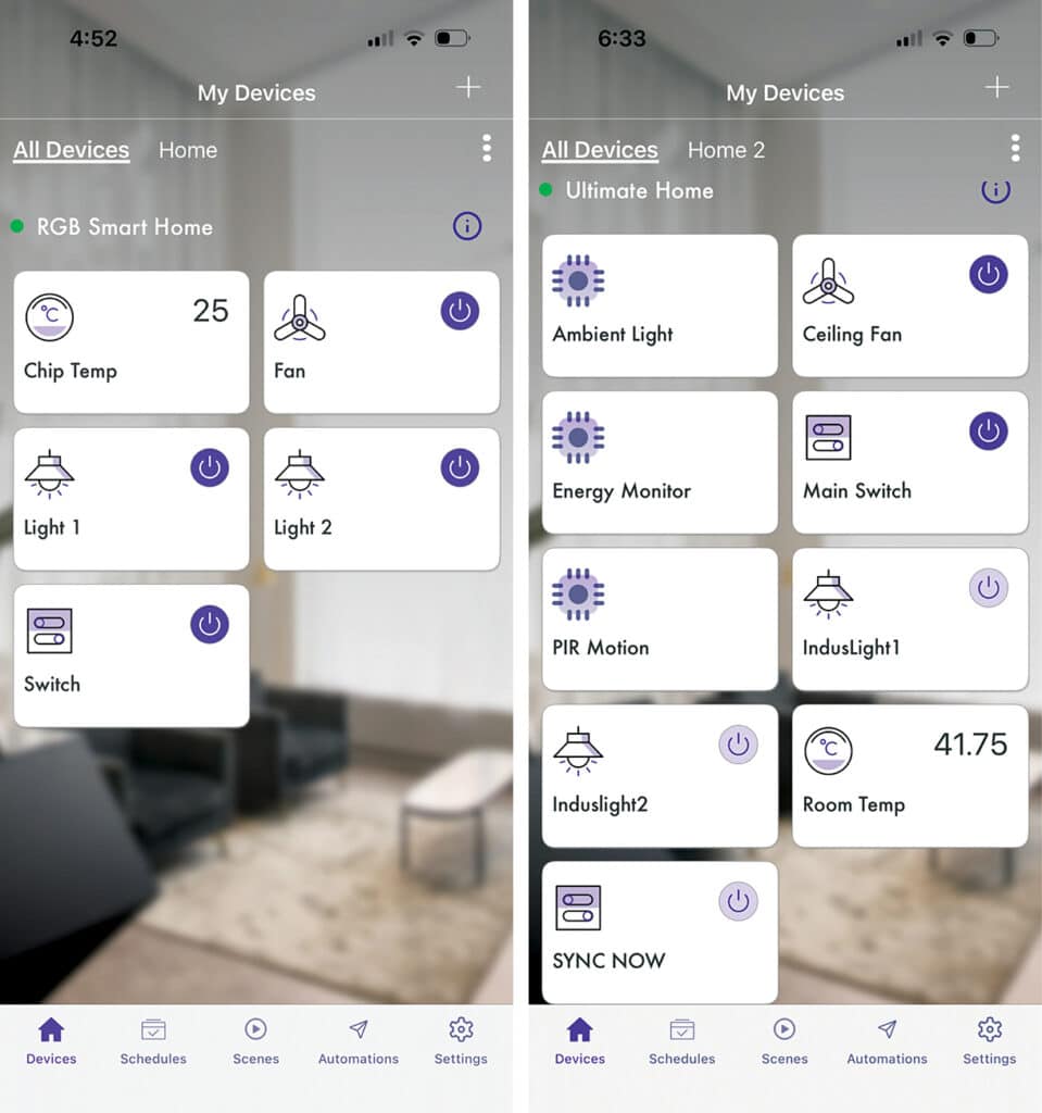
The devices can now be viewed in the RainMaker app for control and monitoring, including million-colour light control, fan speed control, switches, and temperature monitoring. Additional sensors, such as motion, light, or actuators, can be added by modifying the code and repeating the provisioning process.
Fig. 7 shows the app UI displaying all devices for control and temperature monitoring, along with an additional customised device UI showing electricity consumption, energy usage, light status, and other sensor data.
Adding Device to AI Assistant
The system can be integrated with AI assistants such as Alexa, Apple Home, and Google Assistant to enable voice control and automation.
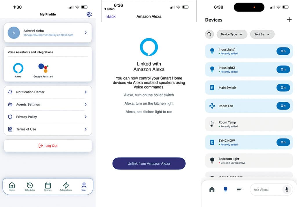
To integrate with Alexa or Google Assistant, go to User Options and select the appropriate option. Follow the on-screen instructions. In this example, the device is linked to Alexa. Sign in to an Alexa account to complete the linking process.
Once linked, the device appears under the ‘Devices’ section in the Alexa app. Custom voice commands and automation routines can then be created using the app. Fig. 8 shows the device linking process and the Alexa app displaying the linked devices.
Testing AI Home Automation System
After uploading the code and connecting the power supply, the system is ready for testing. This system functions as a production-ready platform suitable for mass deployment.
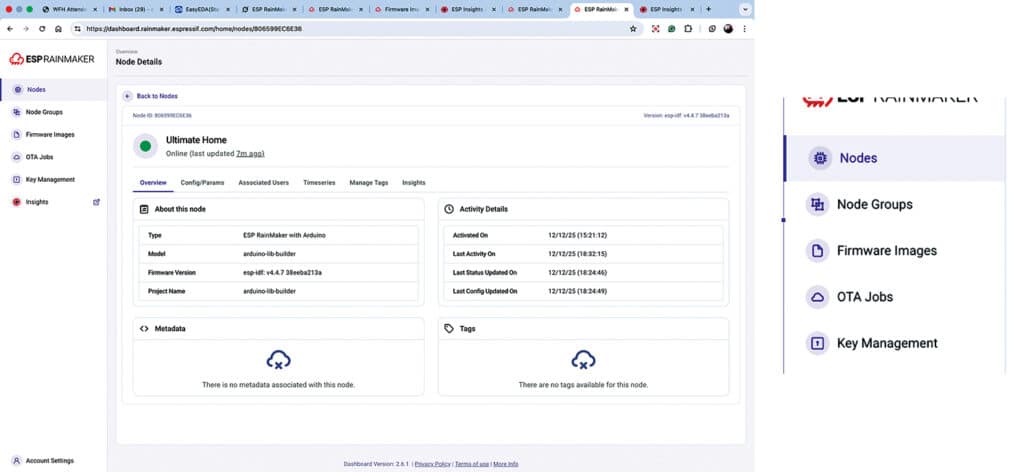
It provides a comprehensive dashboard, device insights, and a device management framework for clients. Using the RainMaker platform, devices can be monitored, crash reports reviewed, and firmware updates delivered remotely.
Log in to the RainMaker dashboard at https://dashboard.rainmaker.espressif.com to view all registered devices, their status, and available insights. It is possible to track how many devices are online, operating correctly, requiring restarts, or experiencing software issues. These insights support effective technical support and over-the-air (OTA) firmware updates.
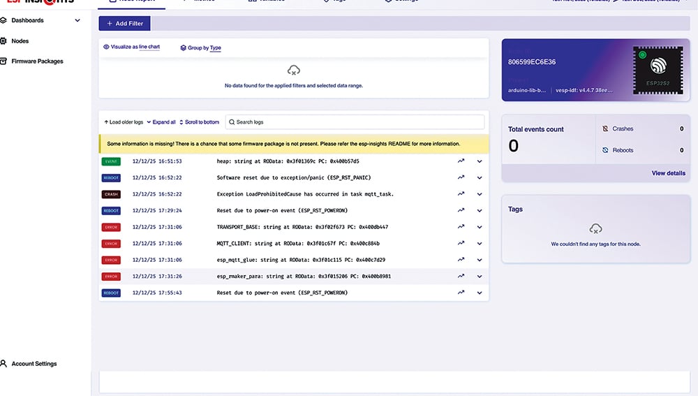
Fig. 9 shows the RainMaker dashboard displaying device insights, while Fig. 10 shows firmware management and OTA updates.
End users or system integrator clients can control the devices using the RainMaker Home app or a custom client application. Elements such as lights, fans, actuators, and sensors are automatically displayed in the app interface based on the firmware configuration.
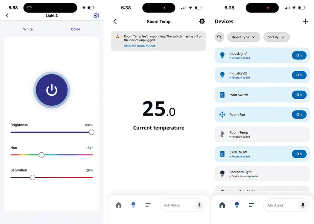
This system includes full RGB pixel LED control with 16 million colours, two switches, and a fan with speed control and temperature sensing. All parameters can be monitored and controlled through the app interface. Light colour, brightness, and on/off state can be adjusted through the app, and the same controls are available via the Alexa app or voice commands.
For example, saying, “Alexa, turn the room light to green or warm white and set the brightness to 80 per cent,” performs the requested action. The fan can also be controlled through the app or voice commands.
Fig. 11 shows the RainMaker Home app interface for light colour and brightness control, alongside the Alexa app displaying current room temperature and device control options.