


Micropython on ESP8266
Micropython is very similar to python 3, only it is targeted for microcontrollers. So, if you know how to program in python, you will find it easy to start with micropython. Micropython also comes with an interactive REPL (Read-Evaluate-Print-Loop), which is an amazing feature that allows you to connect to a microcontroller, execute code quickly without the need to compile or upload code and gives immediate feedback. Also, most importantly the community support makes the use of this firmware more easy.

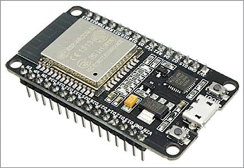
Flash Micropython firmware on the board
The official website for micropython firmware for the board is http://micropython.org/download/#esp8266. Download the latest .bin file under the heading stable firmware.
Now to flash the firmware onto the board will need another tool esptool . Now at command prompt use the below syntax to get the python based tool.
$ pip install esptool
Connect nodemcu to your system and need to identify the port to which it is connected. If you are using a linux based system, below command will help you identify the port.
$ dmesg | grep tty
Next we need to clean all board before flashing the micropython firmware, with the below syntax. Note the port identified in the above step in used in the syntax as –p.
$ ~/.local/bin/esptool.py -p /dev/ttyUSB0 erase_flash
With the clean board we are ready to flash the latest firmware downloaded.
~/.local/bin/esptool.py –port /dev/ttyUSB0 –baud 460800 write_flash –flash_size=detect 0 esp8266-20210202-v1.14.bin
Note: esp8266-20210202-v1.14.bin is the firmware name downloaded, needs to be replaced with the name of the firmware file in your system.
W”ola !! our board is ready, we can enter the REPL prompt and explore, but to enter the REPL prompt we need another CLI tool named picocom.
$ sudo apt-get install picocom
Now to enter the start REPL :
$ picocom /dev/ttyUSB0 -b115200
The above syntax will make some information on the ESP board displayed press ctl + B to enter the REPL prompt.
The command to soft reset the board from the REPL prompt is ctl + D
Also, to push file from your system onto the board we will need another cli tool, adafruit-ampy, and to install it in your system, use the below syntax.
$ pip install adafruit-ampy
$ pip install adafruit-ampy –upgrade
Picoweb framework of micropython
Picoweb is a micro web framework for micropython. If you are acquainted with Flask web framework in python, you will find it very similar to work with. Some of the features of Picoweb are :
- Asynchronous, which means, it can handle multiple concurrent requests.
- Small memory usage
Now to install the framework in nodemcu, Clone the repo to a location in your system.
$ git clone https://github.com/peterhinch/micropython-samples
Dependencies of picoweb framework
To install the framework onto the board, we need to first install few dependencies, open the REPL prompt as mentioned earlier and install the packages as mentioned below.
$ import upip
$ upip.install(‘micropython-uasyncio’)
$ upip.install(‘micropython-ulogging’)
$ upip.install(‘micropython-pkg_resources’)
$ upip.install(‘utemplate’)
Time to step out of REPL, using ctl + A + X, and copy some file into the board from the local system. Move to the folder where the picoweb repo from git is downloaded, check out for the files __init__.py and utils.py. We need to copy these files to the picoweb directory on the board. To do this we will make use of the other cli tool we installed before, adafruil-ampy.
Step1. Create the picoweb directory :
$ ampy –port /dev/ttyUSB0 mkdir picoweb
Step 2. Copy the files from the local system to the picoweb directory on the board.
$ ampy –port /dev/ttyUSB0 put __init.py /picoweb/__init__.py
$ ampy –port /dev/ttyUSB0 put utils.py /picoweb/utils.py
Create API endpoints using picoweb framework
Now we need to create the python script by the name main.py, which will have 2 sections, first to connect to the available wifi and second to create the api endpoint to control the GPIO pin state of the board. We will also create an Access Point for the board, so that if there is no wifi available, we can still connect to the board AP and control the state of the GPIO pins.
$ sudo nano main.py
import picoweb
import network
from machine import Pin
import time
ip=[]
app = picoweb.WebApp(__name__)
#create the Access Point
ap = network.WLAN(network.AP_IF)
ap.active(True)
ap.config(essid=’espAP’, password=’espAPpassword’)
myip = ap.ifconfig()
print(myip)
#connect to the available wifi networks
station = network.WLAN(network.STA_IF)
station.active(True)
station.connect(“wifi-network-name”,”wifi-network-password”)
myip2 = station.ifconfig()
print(myip2)
def qs_parse(qs):
parameters = {}
ampersandSplit = qs.split(“&”)
for element in ampersandSplit:
equalSplit = element.split(“=”)
parameters[equalSplit[0]] = equalSplit[1]
return parameters
#create the api endpoint to control the pin provided as parameter on API call
@app.route(“/pin_ctl”)
def index(req, resp):
queryString = req.qs
parameters = qs_parse(queryString)
print(parameters)
x= int(parameters[‘pin’])
pin = machine.Pin(x, machine.Pin.OUT)
pin.value(0)
time.sleep(0.5)
pin.value(1)
time.sleep(0.5)
pin.value(0)
time.sleep(0.5)
pin.value(1)
time.sleep(0.5)
yield from picoweb.start_response(resp)
yield from resp.awrite(“done”)
if __name__ == “__main__”:
app.run(debug=True,host=”0.0.0.0″,port=80)
Step 3. Copy the file to the board using the below syntax :
$ ampy –port /dev/ttyUSB0 put main.py
Connect and operate from anywhere.
Restart the board and Eureka !!! our API server to control the GPIO over the wifi is done.
Login to the wifi homepage and check the IP address assigned to the device and put the same in any browser, add to the end the pin you want to control as parameter. Follow the example shown below :
$ http://192.168.1.14/pin_ctl?pin=3
Amazing ground up explanation Joy! This should make easy to set up the API server and use Micropython!
Thank you for your valuable feedback