Imagine holding a portable Ammeter and Energy Meter in the size of a coin, just 3.3 cm in diameter, capable of performing the same functions as a bulky multimeter but with even more advanced features.
This ingenious device is not just portable but also incredibly powerful, designed to measure real-time AC and DC currents, calculate energy usage for both AC and DC by simply inputting the voltage, and even determine the frequency of an AC power supply.
It’s an all-in-one solution packed into a tiny form factor, made possible by the IndusBoard Coin equipped with ESP microcontroller technology.
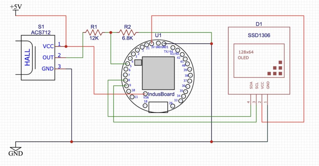
Here the OLED display connects to the IndusBoard to provide real-time readings, and the touch-sensitive pin (pin 4 on the Coin) allows users to switch between modes:
- AC Current Measurement
- DC Current Measurement
- Frequency Calculation (AC)
- Energy Usage Monitoring (AC and DC)

Bill of Material
Here in design we use the following components. Aprat from these you also need some case to put the device in enclosure or you can design your own custom enclosure.
| Components | Quantity |
| IndusBoard Coin (U1) | 1 |
| ACS712 (S1) | 1 |
| Resistor 12K , 6.6K (R1,R2) | 2 |
| SSD1306 (D1) | 1 |
| Battery | 1 |
| Alligator Connector | 1 |
Portable Ammeter – Connection
Connect the Current Sensor (ACS712):
- Connect the VCC and GND pins of the sensor to the 5V and GND pins of the IndusBoard.
- Use the resistors to create a voltage divider circuit for the sensor’s output and connect the divided output to the IndusBoard’s ADC pin.
Attach the OLED Display:
- Connect the SDA and SCL pins of the display to the corresponding I2C pins on the IndusBoard (check your board’s pinout).
- Provide power to the OLED display using the 3.3V and GND pins.
Setup the Touch Pin:
- Assign pin 4 of the IndusBoard Coin as the touch-sensitive input. This will allow you to switch modes with a simple touch.
Connect Power:
- Use a battery to power the device for portability. Connect the battery to the IndusBoard’s power input.
Optional:
- Attach alligator clips to the sensor’s input terminals for easy connection to a load. If you prefer, you can use multimeter probes for a professional touch.

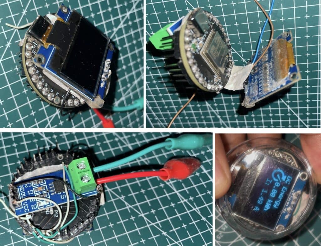
Now solder the components with IndusBoard Coin and fix it as in pic below. Connect the alligator clip to the sensor input if you want else you can also attach probe connector here like Multimeter or Ammeter. Then you can put it inside the small enclosure to make it portable.


Coding
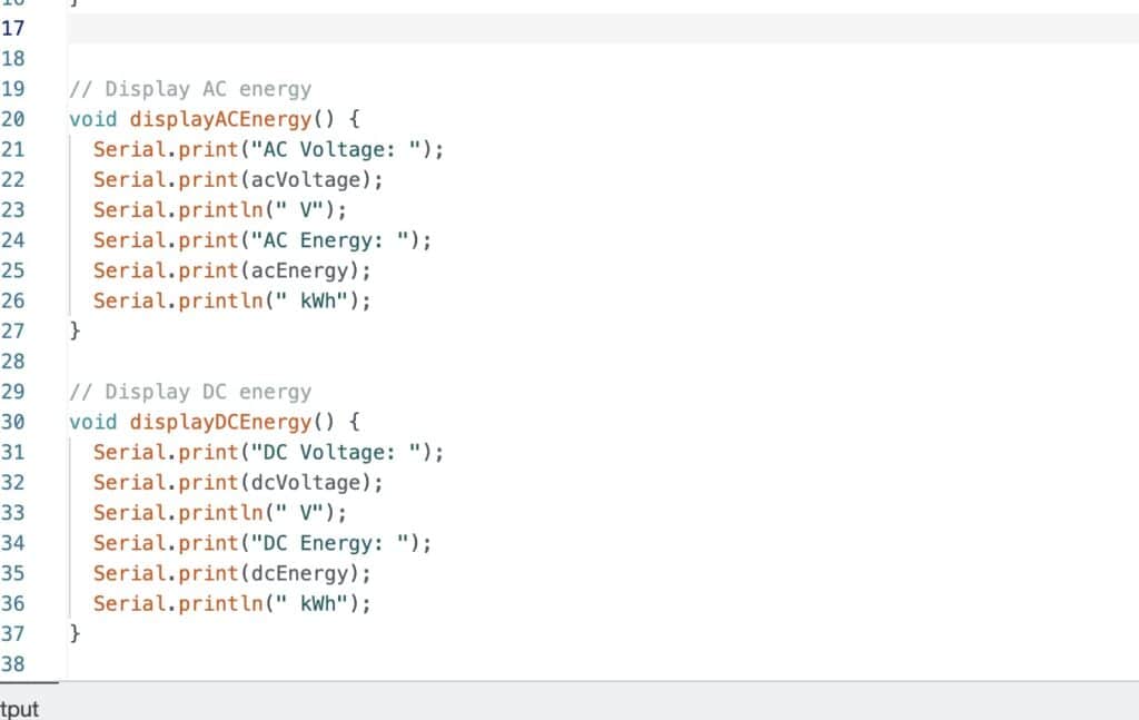
Here in code first the pin number is defined for the touch switch and current sensor then we have to create the function that will handle the touch input and move to functions to calculate different values for different modes.
Then we have created the function that will do calculation for different modes and gives value for that function. Then we have created another function that will update the display in Realtime based of that function and displays the value for current function.
In touch handle function it sense the touch and switch the device into different modes link AC current, DC current and so on for different mode of function.


Testing

Now, power the device and then connect the input of sensor with AC or DC load and then set the mode by touching the pin 4 on Coin and see the readings on display.


