This project presents a portable Arduino-based digital instrument for railway track inspection that measures super elevation (cant), track gauge, and rail temperature. Built around an Arduino Nano, the system uses an MPU6050 IMU for tilt measurement, a VL53L0X laser time-of-flight sensor for gauge measurement, and a DS18B20 digital sensor for monitoring rail temperature.
All measurements are displayed on an SSD1306 OLED, with a single push-button used to switch between modes. Super elevation is calculated using the relation SE = Track Gauge × tan(θ). The system is battery-powered, compact, low-cost, and suitable for field use, offering a digital alternative to manual railway measurement tools. Optional upgrades include Bluetooth connectivity, data logging, and cloud integration for long-term monitoring.
Table of Contents
Railway track laying, construction, and maintenance demand precise measurement of the gauge between two parallel tracks and superelevation, that is, the height difference between rails. For long welded rail tracks, track temperature monitoring is also critical, as rail behaviour is highly sensitive to weather-induced thermal variations. The availability of low-cost sensors and microcontrollers such as Arduino now enables the development of compact digital systems that perform these measurements automatically with improved accuracy.
This system uses an Arduino Nano as the main controller to measure and display track level, its gauge, and temperature. An MPU6050 sensor is employed for tilt (level) measurement, a VL53L0X laser distance sensor measures the track gauge or gap, and a DS18B20 sensor monitors rail track temperature. All measured parameters are clearly displayed on an OLED display, while a single push-button enables switching between different measurement modes.
POC Video Tutorial
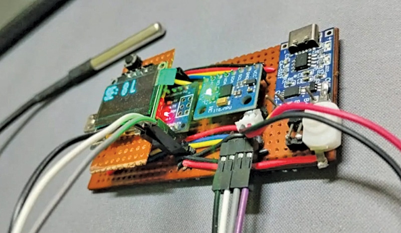
Powered by a small battery, the system is fully portable and well suited for field use. It is intended for hobbyists, field engineers, and DIY enthusiasts who require a simple, reliable, and accurate electronic measuring instrument. Fig. 1 shows the author’s prototype, and the required components are listed in the Bill of Materials table.
| Bill Of Materials | |
| Components | Quantity |
| Arduino Nano (MCU1) | 1 |
| SSD1306 OLED display (OLED1) | 1 |
| MPU6050 IMU sensor (S1) | 1 |
| VL53L0X TOF sensor (S2) | 1 |
| DS18B20 sensor (S3) | 1 |
| 3.7V battery | 1 |
| TP4056 battery charger and power module (U2) | 1 |
| 4.7k resistor (R1) | 1 |
| Push-to-on switch (SW1) | 1 |
Recommended: Buy electronics components online from verified suppliers.
Circuit and Working
Fig. 2 shows the circuit diagram of the digital gauge and super elevation measuring system. The circuit is built around an Arduino Nano (MCU1), a TP4056 module (U2), an SSD1306 OLED display (OLED 1), an MPU6050 IMU sensor (S1), a VL53L0X Time-of-Flight sensor (S2), a DS18B20 temperature sensor (S3), and a few additional components. The Arduino Nano interfaces with three sensors and an OLED display to measure track level, gauge, and temperature. The design is compact and suitable for portable field use.