


3 phase induction motor starter often use star-to-delta converters. The stator coils of the motor are connected in star configuration at the time of power-on and switched to delta configuration when the motor reaches 3/4th of its full speed, after the stator coils have developed sufficient back electromagnetic force (emf).
The 3-phase induction motor starter circuit provides two key advantages:
- Single-phase prevention
- Automatic star-to-delta conversion
It can be used only with those motors which are rated for connection in delta configuration at the given line voltage and which have both ends of each of the three stator windings available individually.

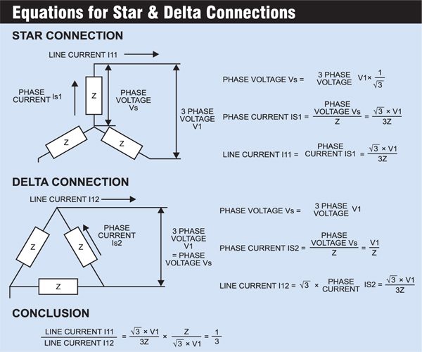
At start, the line voltage is applied to one end of each of the three windings, with the other ends bridged together, effectively connecting the windings in star configuration.
Under this connection, the voltage across the windings is 1/√3 of line-to-line supply voltage and so the current flowing through each winding is also reduced by this factor.

Compared to delta connection, the resultant current flowing from the supply, as also the torque, is reduced by a factor of 1/3 in star configuration. The relevant equations for star and delta connections are given in the box.
As soon as the moment of inertia is overcome, and sufficient back emf is induced in the stator windings, the star connection is opened, and the ends of the windings are connected to the 3-phase supply in a fashion to create a delta connection.
Induction Motor Basics
The AC induction motor, also called the squirrel cage motor, comprises a simple cage-like rotor and a stator containing three windings. The changing field produced by the AC line current in the stator induces a current in the rotor, which interacts with the field and causes the motor to rotate.
The base speed of the AC motor is determined by the number of poles built into the stator windings and the frequency of the AC input voltage. A load on the motor causes the motor to slip in proportion to the load.
3 Phase Induction Motor Starter – Circuit and Working
Fig. 3 shows the circuit of the automatic star-to-delta converter comprising a single-phase preventer and a timer.
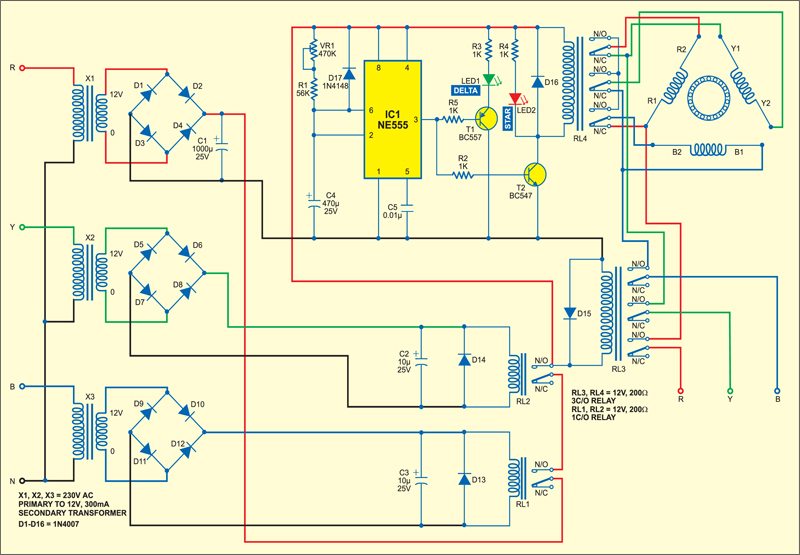
Three single-phase transformers are used to step-down the 3-phase supply separately. Phases R, Y and B are stepped down by transformers X1, X2 and X3 to deliver the secondary output of 12V at 300 mA. The transformer output is rectified by a full-wave rectifier and filtered by a capacitor.
The three 12V DC supplies drive relays RL1, RL2 and RL3, respectively. When all the three phases are present, the 12V DC supply derived from the R phase is fed to the coil of relay RL3 and the timer circuit through the contacts of relays RL1 and RL2. As a result, relay RL3 energizes.
Simultaneously, timer NE555 (IC1), which is configured as a monostable multivibrator, is also triggered. Its time period is determined by capacitor C4, resistor R1 and preset VR1.
Preset VR1 is used to set the time period required to reach 3/4th of the full speed of the motor. The negative triggering pulse for IC1 is provided by the combination of resistor VR1, R1 and capacitor C4.
The timer output at pin 3 is connected to the base of transistor T2 via resistor R2. As a result, transistor T2 is driven to saturation and relay RL4 energizes (indicated by glowing of LED2).
Thus, at power-on, relay RL3, as also RL4, energizes (if all three phases are present) to connect the stator windings in star configuration.
On tracing the connections, you will observe that R phase is connected to R1 end of R windings, Y phase is connected to Y1 end of Y windings and B phase is connected to B1 terminal of B stator windings. The other ends of all the stator windings (i.e., R2, Y2 and B2) get bridged together to form star connection.
After the specified delay, which is provided for the speed of the motor to 3/4th of its full speed value, the monostable output goes low to cut off transistor T2 and de-energize relay RL4. The motor stator coils now switch to delta configuration.
Now you will observe that R phase gets connected to the junction of R1 and B2 terminals, Y phase is connected to Y1 and R2 terminals and B phase is connected to B1 and Y2 terminals of the stator winding.
This connection conforms to delta configuration. Since the output of IC1 is low in this state, pnp transistor T1 is forward biased to light up LED1 and indicate delta configuration.
Relay Configuration
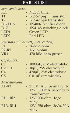
RL1 and RL2 are normal control relays, which are used to energize relay RL3. PCB-mounted OEN Type 57 relays rated for 12 volts (or equivalent) may be used for the purpose. RL3 and RL4 are required to support the complete line current during star as well as delta configurations.
Hence the contacts must be rated to withstand full line-to-line voltage and expected full current of the motor in delta configuration.
Thus, heavy-duty power relays of appropriate voltage and current rating for 12V coils must be used. The relays are to be mounted outside the PCB on the chassis of a suitable metal cabinet, which must be earthed properly to avoid any risk of shock.
Before connecting the motor to the circuit, proper operation of the relays must be checked. The windings must be connected as shown in the circuit diagram.
PCB Design
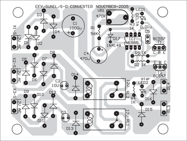
A single-side PCB for the automatic 3 phase induction motor starter circuit is shown in Fig.4 and its component layout in Fig. 5.
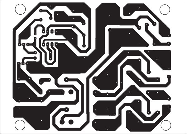
Download PCB and component layout PDFs: click here

Thanks
Status of 7th pin of 555
Kindly elaborate your query.
is there any connection at pin 7 of 555 timer?
what components are connected in place of Y1, Y2, B1, B2, R1, R2…?
sorry, i forgot that ryb are the windings of three phase induction motor.
How to protect this circuit for the motor and what are the advantages for this circuit?
What is the benifit of this circuit ?
Which is the benifit for this circuit?
Can you share Gerber file and schematic to upgrade and simulate it in Circuit designing software and Simulate.