


 Consider that a school has a total of eight periods with a lunch break after the fourth period. Each period is 45 minutes long, while the duration of the lunch break is 30 minutes. To ring this automatic school bell to start the first period, the peon needs to momentarily press switch S1. Thereafter, the bell sounds every 45 minutes to indicate the end of consecutive periods, except immediately after the fourth period, when it sounds after 30 minutes to indicate that the lunch break is over. When the last period is over, LED2 glows to indicate that the bell circuit should now be switched off manually.
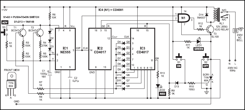
In case the peon has been late to start the school bell, the delay in minutes can be adjusted by advancing the time using switch S3. Each pushing of switch S3 advances the time by 4.5 minutes. If the school is closed early, the peon can turn the bell circuit off by momentarily pressing switch S2.The bell circuit contains timer IC NE555 (IC1), two CD4017 decade counters (IC2 and IC3) and AND gate CD4081 (IC4). Timer IC1 is wired as an astable multivibrator, whose clock output pulses are fed to IC2.

IC2 increases the time periods of IC1 (4.5 and 3 minutes) by ten times to provide a clock pulse to IC3 every 45 minutes or after 30 minutes, respectively. When the class periods are going on, the outputs of IC3 switch on transistors T1 and T2 via diodes D4 through D12.
Resistors R4 and R5 connected in series to the emitter of npn transistor T2 decide the 4.5-minute time period of IC1. The output of IC1 is further connected to pin 14 of IC2 to provide a period with a duration of 45 minutes. Similarly, resistors R2 and R3 connected in series to the emitter of npn transistor T1 decide the 3-minute time period of IC1, which is further given to IC2 to provide the lunch-break duration of 30 minutes.

Initially, the circuit does not ground to perform its operation when 12V power supply is given to the circuit. When switch S1 is pressed momentarily, a high enough voltage to fire silicon-controlled resistor SCR1 appears at its gate. When SCR1 is fired, it provides ground path to operate the circuit after resetting both decade counters IC2 and IC3. At the same time, LED1 glows to indicate that school bell is now active.
When switch S2 is pressed momentarily, the anode of SCR1 is again grounded and the circuit stops operating. In this condition, both LED1 and LED2 don’t glow.
When the eighth period is over, Q9 output of IC3 goes high. At this time, transistors T1 and T2 don’t get any voltage through the outputs of IC2. As a result, the astable multivibrator (IC1) stops working.
The school bell sounds for around 8 it sounds after 30 minutes to indicate that the lunch break is over. When the last period is over, LED2 glows to indicate that the bell circuit should now be switched off manually.
In case the peon has been late to start the school bell, the delay in minutes can be adjusted by advancing the time using switch S3. Each pushing of switch S3 advances the time by 4.5 minutes. If the school is closed early, the peon can turn the bell circuit off by momentarily pressing switch S2.
The bell circuit contains timer IC NE555 (IC1), two CD4017 decade counters (IC2 and IC3) and AND gate CD4081 (IC4). Timer IC1 is wired as an astable multivibrator, whose clock output pulses are fed to IC2. IC2 increases the time periods of IC1 (4.5 and 3 minutes) by ten times to provide a clock pulse to IC3 every 45 minutes or after 30 minutes, respectively. When the class periods are going on, the outputs of IC3 switch on transistors T1 and T2 via diodes D4 through D12.
Resistors R4 and R5 connected in series to the emitter of npn transistor T2 decide the 4.5-minute time period of IC1. The output of IC1 is further connected to pin 14 of IC2 to provide a period with a duration of 45 minutes. Similarly, resistors R2 and R3 connected in series to the emitter of npn transistor T1 decide the 3-minute time period of IC1, which is further given to IC2 to provide the lunch-break duration of 30 minutes. Initially, the circuit does not ground to perform its operation when 12V power supply is given to the circuit.
When switch S1 is pressed momentarily, a high enough voltage to fire silicon-controlled resistor SCR1 appears at its gate. When SCR1 is fired, it provides ground path to operate the circuit after resetting both decade counters IC2 and IC3. At the same time, LED1 glows to indicate that school bell is now active.
When switch S2 is pressed momentarily, the anode of SCR1 is again grounded and the circuit stops operating. In this condition, both LED1 and LED2 don’t glow.
When the eighth period is over, Q9 output of IC3 goes high. At this time, transistors T1 and T2 don’t get any voltage through the outputs of IC2. As a result, the astable multivibrator (IC1) stops working.
The school bell sounds for around 8 seconds at the end of each period. One can increase/decrease the ringing time of the bell by adding/removing diodes connected in series across pins 6 and 7 of IC1.
The terminals of the 230V AC electric bell are connected to the normally-open (N/O) contact of relay RL1. The circuit works off a 12V regulated power supply. However, a battery source for back-up in case the power fails is also recommended.
More interesting projects available here.


Excellent. Thanks to enlighten with remarkable item. The information is very educative.
great!!! is there any software required for working
No, you do not need any software for this project.
please send pcb layout
Can you give me the theratical explanations for the working of this circuit with equations and all…
sir Iwant to learn to prepare automatic school bell and water level controller
sir plz give me advantages and disadvantages
How do we get time periods of 3min,4.5min
Plz reply me I have a question
Kindly elaborate your query.
How to change the hour time? For example if class hour 50 min
I want to add break period for every two completed hour how to add it this circuit
How to set a time to ring a bell after two minutes
On which breadboard we have to give connections
Give the type of breadboard used for this circuit