


The eFuse helps engineers protect high-voltage circuits, monitor current, and connect or disconnect batteries safely. Can this design simplify the eMobility systems?
High-voltage eMobility applications demand precise, reliable protection for both users and hardware. Mechanical relays, contactors, and traditional non-resettable fuses are limited by slow response times, large size, and one-time-use constraints. For design engineers, these limitations make it difficult to build compact, safe, and efficient high-voltage systems. Semiconductor-based resettable fuses, or eFuses, provide a solution by combining fast overcurrent protection, continuous monitoring, and repeated operation without replacement.
A reference design from Vishay demonstrates how an eFuse can handle up to 40 kW of continuous power with minimal energy loss. Using SiC MOSFETs as primary switches and an optocoupler for control, the design operates with under 30 W of losses and does not require active cooling. The eFuse protects the system by shutting down in under 2.5 µs during overcurrent events. It also includes a preload function, monitors current continuously, and detects excessive load capacitance or short circuits during power-up, providing immediate shutdown when needed.

The eFuse is specifically designed to safely connect and disconnect high-energy battery packs to vehicle loads. The SiC MOSFETs can carry continuous currents up to 100 A. When current exceeds the preset limit, the eFuse quickly disconnects the load, protecting both the battery and the user. This fast response is crucial for high-voltage applications, where even brief overcurrent conditions can damage components or create safety risks.
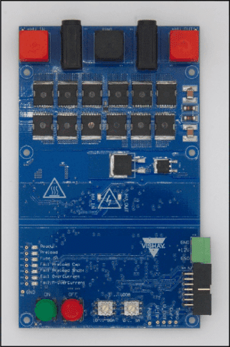
The design is implemented on a double-sided, four-layer FR4 PCB with 70 μm copper per layer, measuring 150 mm × 90 mm. High-voltage components, including 12 SiC MOSFETs, connectors, control buttons, status LEDs, and test points, are located on the top layer. Low-voltage control circuitry resides on the bottom layer. Heat generated by the MOSFETs is conducted through thermal vias to a solid copper layer on the back and then transferred to an electrically isolated heat sink, ensuring safe thermal management.

For safety, the low-voltage supply must be enabled before the high-voltage input. An LED indicates when the system is live. High-voltage components are powered via the low-voltage control side while maintaining galvanic isolation. This is achieved by generating two 0–12 V AC signals at 200 kHz on the control side, transferring them capacitively across the isolation barrier using ceramic capacitors, and rectifying them back to the original supply voltage on the high-voltage side.
The eFuse can also be remotely monitored and controlled through a web interface, giving engineers flexibility during testing and operation. This combination of fast protection, continuous monitoring, thermal safety, and remote control makes the eFuse a practical solution for high-power eMobility applications, addressing both design and operational challenges.
Vishay has tested this reference design. It comes with a bill of materials (BOM), schematics, assembly drawing, printed circuit board (PCB) layout, and more. The company’s website has additional data about the reference design. To read more about this reference design, click here.
