 A drone assists us in performing various complex tasks with ease. But there are certain tasks that we want to be executed automatically rather than manually – without much effort.
To accomplish this, I have decided to make a smart drone that can be programmed with instructions and coordinates, allowing itself to be driven to its destination without any human effort.
NOTE:- Conducting pre-programmed missions using autonomous UAVs and drones is strictly prohibited in some regions/countries. Please obtain the confirmation policies and UAV flying rules of that area before proceeding with the project.

The following project is strictly for education purposes only.
Assembly of Drone Components
Frame Assembly
For this project, a QAV250 drone frame is being used as it is small, lightweight and easy to control. However, you can use a larger drone frame like an F450 for carrying loads such as parcels.
The QAV250 drone frame consists of:
- Base plate x 2
- Motor arm x 4
- Top plate x 1
- Landing gear x 4
Place all the four motor arms between the two base plates and firmly screw them. Next, assemble the landing gears into the arms and fit the top plate on the base plate. Now the frame is ready to be equipped with components (See below figure)
Next, connect the ESC wires to the power distribution board along with the XT60 plug (as shown in the below picture). Place the power distribution board in the middle of the QAV450 frame. Affix the ESC on each arm of the Quad 250 frame as shown in the picture below. After that, tighten all the 200kv A2212 motors on the drone frame.
Attaching Motor and ESC on Drone Frame
Place motors on each arm of the drone frame and then place the ESC on the drone frame. After that, set the flight controller.
Setting Flight controller Battery and GPS Module Of Drone Frame
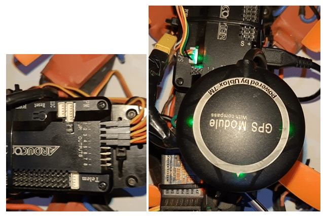
Place the LiPo battery at the center of the drone frame and mount the flight controller on top of it (next to the u-blox GPS module) using a mounting rod. Next, attach the radio receiver on the drone frame as shown below:
Connection
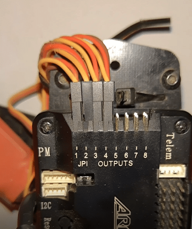
The ArduPilot Mega (APM), on one side, has several pins for motor and servo outputs, and for radio receivers on the other side. At the top, it has a series of USB pins for connecting various sensors and accessories to drones like optical flow sensors, LiDARs etc.
The APM flight controller also has a port plug for GPS.
As shown in the picture below, connect the Radio Receiver channel pin to APM Radio inputs. Next connect the 3-wired ESC servo motor pins to the output pins, keeping in mind the signal pin of ESC should go to the signal pin of APM (the signal pin on APM is marked in my case to keep the pin on the top side as shown in picture).
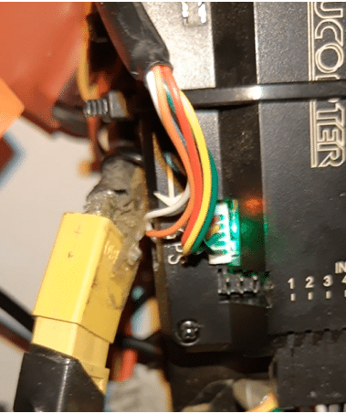
Next, plug the Ublox Neo 7M GPS module into the GPS port present on the APM. The GPS module has two plugs with wires: one for GPS and power, and the other for compass.
APM Preparation For UAV
The APM can be prepared using many different software. One of the common ones is Mission Planner. Download the latest version of the software and install it on your PC.
Next, update the APM flight controller with the latest firmware. To do so, open the Mission Planner software and connect the USB to APM and PC.
Note:- For first-time setup, do not click on the ‘Connect’ option (present at right-hand corner of the screen) as it will connect the Mission Planner to APM at that moment. Because the board is empty and without firmware, first do the initial setup, that is, upload the relevant firmware.
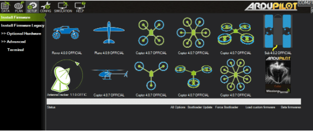
After that, select the UAV that you want to create (here, a quad x type is being made so that is selected). Now the Mission Planner starts uploading the firmware to the APM.
After successfully updating the firmware, we can now connect the Mission Planner using the connect button on the right-hand screen corner.
Mission Planner Settings
After connecting the APM with the Mission Planner software, select the vehicle type: x or tri (since type x quad is being used here, so this is selected).
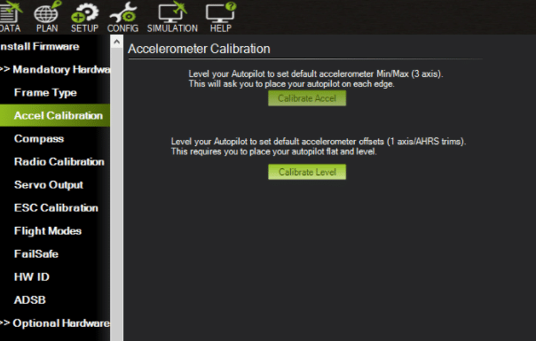
To set up the hardware, first calibrate the ACC. For this, go to Accelerometer and select ‘Live Calibrate Now’. Then put the flight to left, right, nose-down, nose-up and backwards.
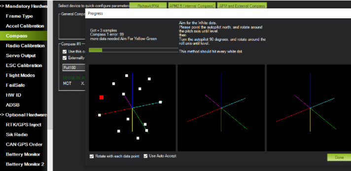
Compass Calibration
To calibrate the compass, select ‘Compass’ and then go to ‘Live Calibration’. Here, an external compass is being used so remove the jumper from APM next to GPS.
Next, move and rotate the drone in all directions to connect the path in GUI of Mission Planner. After connecting all the paths and points, the compass is calibrated.
After this, go to Radio Calibration and select ‘Live Calibration Now’. Move the lines and channels of the remote to maximum and minimum positions. Click Done to finish calibrating the APM.
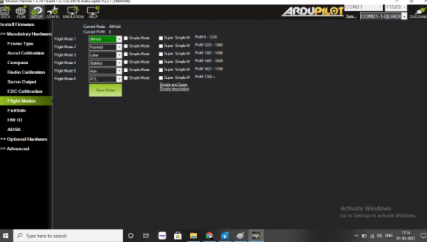
Setting Flight Modes
Here we can set any flight modes as per our wish. Since the Mission Planning software is being used, we will set the AUO, Loiter Alti Hold, Position Hold and then save them.
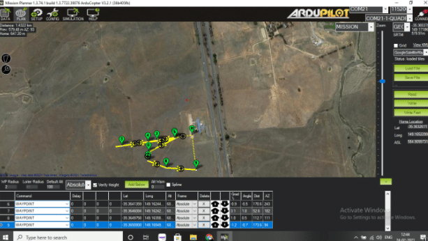
Mission Planning 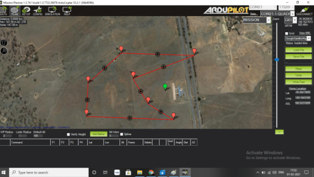
In the Mission Planner software window, select ‘Plan’. It will display the live location of the drone.
To plan a specific mission, simply create the points/paths for the drone, select them, save and then run.
Testing
Set the flight mode to auto and specify the path on the Mission Planner software. Next, arm the drone using a remote control to test features such as automatic flight and the ability to return after completing a mission. This system is effective for spraying or surveying purposes using drones.
Now the mission planning UAV/drone is ready.