 This toy organ for children uses a readily-available force-sensitive resistor (FSR) and an NE555 timer IC. Resistance of the FSR varies with the amount of force or pressure being applied on its surface to play the toy organ.
Circuit and working
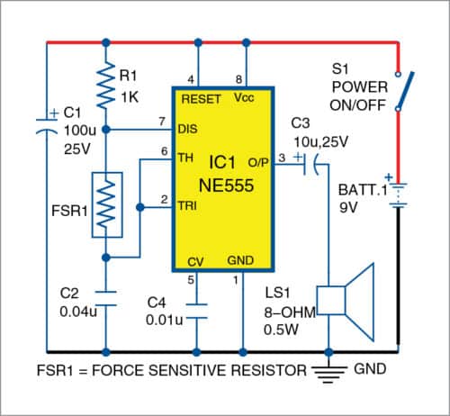
The circuit diagram of the force-operated toy organ is shown in Fig. 1.

It is built around force sensor FSR1, timer NE555 (IC1), small loudspeaker LS1 and a few other components.
Here, FSR1 is connected between pins 6 and 7 of NE555, which is wired in astable multivibrator mode. NE555 acts as an oscillator that produces square-wave signals in audio range.

Normally, FSR1’s internal resistance is above 100-kilo-ohm. When force is applied on its surface by pressing it with a finger, its resistance decreases and audio frequency or oscillation changes. So, by applying different pressures on FSR1, different audio tones are generated that can be heard in LS1.
Construction and testing
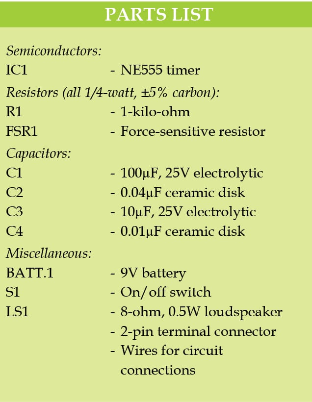
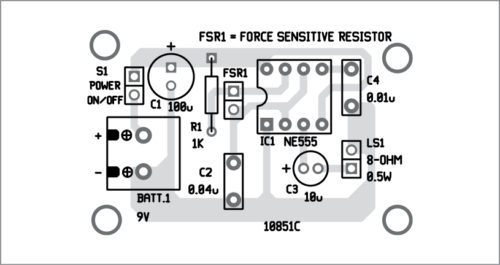
The PCB layout for the force-operated toy organ is shown in Fig. 2 and its components layout in Fig. 3. Assemble the circuit on the PCB. Connect a 9V battery across BATT.1 and FSR1 using external wires. As soon as the circuit is powered on, sound will be heard from the speaker.


Download PCB and Component Layout PDFs: click here
Place FSR1 on a flat surface so that force can easily be applied on the active surface to produce various tones. The 38mm (1.5-inch) force sensor used in this project is shown in Fig. 4.

It has two pins extended from the active surface for connection to a breadboard or circuit.


