


Almost all electronic gadgets now come with one or more USB ports. You can use the USB port as an automatic switch to control devices powered by mains. Here we present a USB controlled power switch circuit that can control the mains power of an LED TV and a DTH set-top box (STB).
Generally, mains power for TV and STB are derived from a common switchboard. When you switch off the power of the TV using a remote control or sleep timer in the TV, the switched-mode power supply (SMPS) of the TV continues to draw a small amount of power from mains and the STB does not get switched off. This drawback can be overcome using this circuit. Besides, it protects the devices from harmful initial surges when power comes back after a power failure.
USB controlled power switch circuit
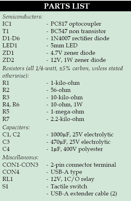
Circuit diagram of the automatic USB controlled power switch is shown in Fig. 1. It is built around optocoupler PC817 (IC1), transistor BC547 (T1), 12V 1C/O relay (RL1), six rectifier diodes 1N4007 (D1 through D6) and a few other components. USB-A extender cables are used to connect the USB ports of the TV and of the STB to the circuit.

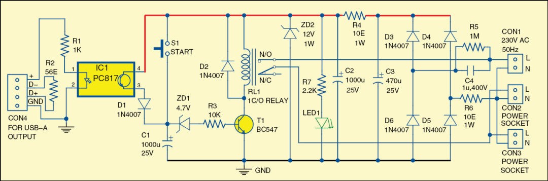
230V AC mains power supply connector CON1 is connected between n/o contacts of relay RL1 and neutral line N. When switch S1 is pressed, it allows positive voltage to timing capacitor C1 and the power to go through the connected zener diode ZD1 and resistor R3 to the base of transistor T1. When transistor T1 gets base-bias voltage, it conducts and relay RL1 energises to provide 230V AC mains to power sockets CON2 and CON3, which are used to connect an LED TV and STB, respectively.
When the LED TV (connected across CON2) and the STB (connected across CON3) get 230V AC mains power, USB port of the TV (connected across CON4) gets power to enable IC1. Timing capacitor C1 gets positive supply voltage through diode D1 and it remains charged until mains power of the LED TV is disconnected.
When you switch off the TV using its remote control, power that was available at its USB port connected across CON4 also stops. So 5V voltage available to the optocoupler stops. T1 stays on for a predetermined time (about 100 seconds) only due to the charged timing capacitor C1. If you wish to keep it on for longer, use higher-value capacitor C1. After the capacitor has discharged, the complete system gets switched off.
Download PCB and component layout PDFs: click here
There are two benefits of using the timing capacitor. The first is to protect the gadgets from harmful power surges that may occur while switching on using switch S1. The second is, when you use sleep timer mode of the TV, you can switch on the LED TV without pressing switch S1 again, if the time lapses before you sleep.
Finally, working of the circuit is simple. Press switch S1 momentarily to activate the TV LED and STB. When you switch off the TV using the remote control, both the TV and STB will get switched off.
Construction and testing
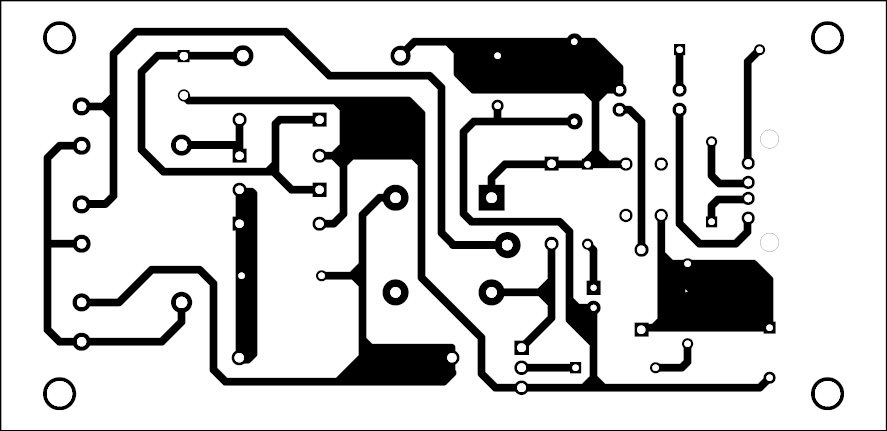
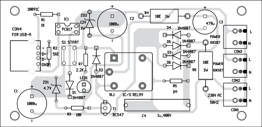
A single side PCB for the automatic USB controlled power switch is shown in Fig. 2 and its component layout in Fig. 3. Enclose the PCB in a small box in such a way that you can connect it to TV’s and STB’s USB ports. Also provide connectors for CON1 through CON3.
Feel interested? Check out other electronics projects.
Can you provide us with the BitMaP image of the PCB layout
You can send your request to [email protected]