


The higher four bits (D7 down through D4) of this command are always ‘1000,’ while lower four bits (D3 down through D0) decide selection of CG-ROM or RAM and how the graphic display is merged with text display. To use both the 128-character on-chip character-generator ROM (CG-ROM) and the 128-character external CG-RAM function, set D3 to ‘0.’ To use only the 256-character CG-RAM user-defined character generator, set D3 to ‘1.’
D0 through D2 set the mode through which the text area is merged with the graphics area. Text attributes can only be used in the text-only mode as the attribute data is stored in the graphics area.
D0 through D2 should be selected as per the need of merging graphics with text.
[stextbox id=”grey”]
Logically ‘OR’ of text with graphics 0 0 0
Logically ‘EXOR’ of text with graphics 0 0 1
Logically ‘AND’ of text with graphics 0 1 1
Text only (with attribute data in graphics area) 1 0 0
[/stextbox]
Description of ‘display mode set’ commands (command byte only)
This command does not require any data byte.
The higher four bits (D7 through D4) of this command are always ‘1001,’ while the lower four bits (D3 through D0) decide the cursor operation.
[stextbox id=”grey”]
Display off (90H)
D3- ‘0’ means graphic ‘off,’
‘1’ means graphics ‘on’
D2- ‘0’ means text ‘off,’
‘1’ means text ‘on’
D1- ‘0’ means cursor ‘off,’
‘1’ means cursor ‘on’
D0- ‘0’ means cursor blinking ‘off,’
‘1’ means cursor blinking ‘on’
[/stextbox]
After reset, D3 through D0 are reset to zero.
Description of ‘cursor-pattern select’ command (command byte only)
This command does not require any data byte.
The higher four bits (D7 through D4) of this command are always ‘1010,’ while the lower four bits (D3 through D0) decide cursor pattern.
[stextbox id=”grey”]
1 line cursor (A0H)
2 line cursor (A1H)
“ “ “ “ “ “ “ “ “
“ “ “ “ “ “ “ “ “
7 line cursor (A6H)
8 line cursor (A7H)
[/stextbox]
Description of ‘data auto read/ write’ commands (command byte only)
This command does not require any data byte.
The higher six bits (D7 through D2) of this command are always ‘101100,’ while the lower two bits (D1 and D0) decide auto advance mode.
These single-byte commands are very useful when transferring blocks of data to/from the VRAM.
After sending a ‘data auto write’ (B0H) command, it is not necessary to send the data-write instruction for each data byte being written to the VRAM. The ‘data auto-write’ command should be sent after the ‘address pointer set’ command. The address pointer will automatically increment by ‘1’ for each data written. After sending all data, the ‘auto mode-reset’ command (B2H or B3H) should be sent to resume normal operation. When in the ‘data auto-write’ mode, no commands can be accepted, as all the following bytes are assumed to be display data bytes.
After sending a ‘data auto-read’ (B1H) command, it is not necessary to send the data-read instruction for each data byte being read from the VRAM. The ‘data auto-read’ command should be sent after the ‘address pointer set’ command. The address pointer will automatically increment by ‘1’ for each data read. After reading all data, the ‘auto mode reset’ command (B2H or B3H) should be sent to resume normal operation. When in the ‘data autoread’ mode, no commands can be accepted.
[stextbox id=”grey”]
Data Auto Write Set (B0H)
Data Auto Read Set (B1H)
Auto Mode Reset (B2H or B3H)
[/stextbox]
Description of ‘data-read/ data-write’ commands (command byte only)
This command does not require any data byte.
The higher five bits (D7 down through D3) of this command are always ‘11000,’ while the lower three bits (D2 down through D0) decide the pointer-advance mode.
These commands are used to write data to or read data from the VRAM. Data-read or data-write commands should be sent after setting an address by the ‘pointer set’ command. The address pointer may be automatically incremented, decremented or left unchanged depending on which data read/write command is being sent. A datawrite or data-read command is required for each data byte written to or read from the VRAM.
This command should not be confused with B0H and B1H commands. In the case of B0H or B1H command, you need not send a write or read command between each data-write or data-read. But in the case of C0H and C1H commands, after every data write or data read you need to send C0H or C1H for advancing the pointer.
[stextbox id=”grey”]
Data Write – Address Pointer Auto Incremented (C0H)
Data Read – Address Pointer Auto Incremented (C1H)
Data Write – Address Pointer Auto Decremented (C2H)
Data Read – Address Pointer Auto Decremented (C3H)
Data Write – Address Pointer Auto Unchanged (C4H)
Data Read – Address Pointer Auto Unchanged (C5H)
[/stextbox]
Description of ‘screen peeking’ command (command byte only)
This command does not require any data byte.
This single-byte command is used to transfer one byte of displayed data to the data stack and may be read by the microcontroller using a ‘data read’ command. It is useful to read the logical combination of text and graphic data on the LCD screen. The status flag STA6 should be checked after each ‘screen peeking’ command. If the address pointer is not set to the graphics RAM area, the ‘screen peeking’ command is ignored and STA6 is set to ‘1.
[stextbox id=”grey”]Screen Peeking (E0H)[/stextbox]
Description of ‘screen copy’ command (command byte only)
This command does not require any data byte.
This single-byte command is used to copy one row of data displayed on the LCD screen to the graphics RAM area specified by the ‘address pointer set’ command. This ‘screen copy’ command cannot be used if the row of displayed data contains ‘text attribute’ data as set by the ‘mode set’ command. The status flag STA6 should be checked after each ‘screen copy’ command. If the address pointer is not set to the graphics RAM area, the ‘screen copy’ command is ignored and STA6 is set to ‘1.’
[stextbox id=”grey”]Screen Copy (E8H)[/stextbox]
Description of ‘bit-set/ bit-reset’ command (command byte only)
This command does not require any data byte.
The high-order four bits (D7 through D4) are always ‘1111.’
This single-byte command is used to set/ reset individual bits in the RAM. The ‘address pointer set’ command decides which byte is to be operated on. Any one bit in the byte selected can be set or reset. Multiple bits in a byte cannot be set/ reset at the same time. D2 through D0 specifies the location of the bit to be set/ reset. ‘000’ selects the least significant bit (LSB) and ‘111’ the most significant bit (MSB). For resetting the bit, make D3 as ‘0’ and for setting the bit make D3 as ‘1.’
[stextbox id=”grey”]
Bit Reset (F0H-F7H)
Bit Set (F8H-FFH)
[/stextbox]
Circuit description
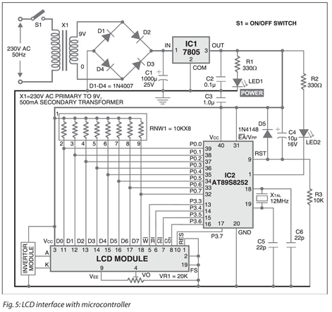
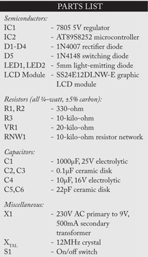
After having understood the basic operation of the LCD module, it is fairly simple to interface it with any micro172 Interfacing A Graphics LCD With The Microcontroller controller. Fig. 5 shows the circuit for interfacing the graphics LCD with the microcontroller. Atmel’s AT89S8252 microcontroller (IC2) is used to interface the LCD module. Port P0 (Pins 39 through 32) of the microcontroller is connected to data lines D0 through D7 of the LCD module. Port P0 pins are pulled high with the 10-kilo-ohm resistor network. This data port is used to send and receive the data between the microcontroller and the LCD module. The control lines and RES pins should be connected to port pins P3.3 through P3.7 of the microcontroller, respectively.
EA/VPP pin of the microcontroller is connected to 5 volts to use the internal flash program memory. The power-on-reset for microcontroller IC2 is achieved through capacitor C4 and resistor R3. Diode D5 connected across capacitor C4 allows short power supply failures. A 12MHz crystal is used for internal oscillator clocks. An LED (LED2) is connected at pin P1 of the microcontroller and acts as the program running indicator.
Font-select pin 19 (FS) of the LCD module is grounded to generate 8×8-character font size.
Preset VR1 is used for contrast variation of the LCD. Normally –7.8V will give good contrast. VEE is a negative supply voltage output from the LCD module that outputs around –14 volts.
The LCD modules have an inbuilt fluorescent tube as backlight source. This needs a special inverter that comes with the LCD module as optional. It works off 5V supply and generates 100-200V AC, which is connected to ‘A’ and ‘K’ terminals of the LCD module. If you opted for the LED backlight module, you may not need this inverter.
The 230V, 50Hz AC mains is stepped down by transformer X1 to deliver a secondary output of 9V, 500 mA. The transformer output is rectified by a full-wave bridge rectifier comprising diodes D1 through D4, filtered by capacitor C1 and regulated by IC 7805 (IC1). Provide adequate heat-sink for 7805 as the LCD backlight draws a significant current. Capacitor C2 bypasses the ripples present in the output. LED1 acts as the power indicator. Resistors R1 and R2 act as the current limiters for LED1 and LED2, respectively.
Software program
The software program presented here for the operation of LCD module is just an example and you have to re-develop it for your application. The software is written in ANSI C language and compiled using KEIL compiler. The program has enough remarks inserted on the lines so you can easily understand what the program instructions are really doing.
Starting from the main line, first the ports are initialised, and then the LED blinks four times to indicate that the program and the hardware are working. Basically, the LCD module is first reset and initialised. After initialisation, the LCD module is loaded with graphics data and then with text data. The graphics data contains a scene of the Sun in the background of a tree and hills. The text inserted is ‘The SUN.’ A blinking cursor is also shown as an example. At the end, the ‘graphic and text on’ command is inserted before ending the program with an infinite wait loop.
Note that no data or command should be written to the LCD module if the module is busy doing its own internal operation. As such a subroutine is inserted before every write operation to check whether the LCD module is busy or free. This is done in the ‘check status’ subroutine where both D0 and D1 bits are checked before proceeding any further.
Also note that:
The LCD module has a built-in CG-ROM with 128 characters possible. You can use this address to insert any text character. For example, ‘21H’ will mean ‘A.’
You can make a graphics ‘.bmp’ file of your choice in ‘paint’ software on a 240×128-pixel paper size and use FONTGEN software to convert the ‘.bmp’ image into graphics data file as required by the LCD module. Copy the graphics data code (generated by FONTGEN software) and paste in the source program at the indicated place. For downloading the FONTGEN, visit www.8052.com .
Download source code: click here
Download actual-size single-side PCB layout and component layout: click here
