


The MAX232 has two internal charge-pumps that convert +5V into ±10V (unloaded) for RS-232 driver operation. The first converter uses capacitor C7 to double the +5V input to +10V on capacitor C9 at pin 2. The second converter uses capacitor C8 to invert +10V to -10V on capacitor C10 at pin 6.
All the serial communication is controlled through special function register SCON. This register contains mode-selection bits, ninth data bit for transmit and receive (TB8 and RB8), and serial-port interrupt bits (TI and RI). Serial communication requires standard baud rate. Timer 1 is configured in the auto-reload mode to generate the baud rate. The baud rate is determined as:
![]()

To derive the power supply, the 230V AC mains is stepped down by transformer X1 to deliver the secondary output of 9V, 300 mA. The transformer output is rectified by a full-wave bridge rectifier comprising diodes D1 through D4, filtered by capacitor C1 and then regulated by IC 7805 (IC3). Capacitor C2 bypasses the ripples present in the regulated 5V power supply. LED1 acts as the poweron indicator and resistor R1 limits the current through LED1.
Download PCB and component layout PDFs: click here
Construction and testing
An actual-size, single-side PCB for microcontroller-based serial data transfer circuit is shown in Fig.3(View as PDF) and its component layout in Fig.4(View as PDF). Assemble the circuit on the PCB to minimise assemble the components and double- check for any overlooked error. Connect the assembled circuit to the COM port available at the back side of a computer. The information stored in the microcontroller is sent to the PC through the COM port using the HyperTerminal program.
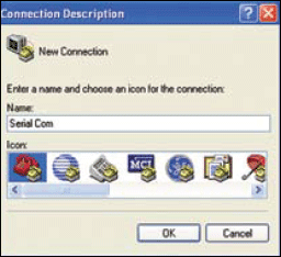
To open the HyperTerminal program, go to Start → Programs → Accessories → Communications → HyperTerminal. You will see a window as shown in Fig. 5. Type in the desired name and click ‘ok.’ Select a COM port (refer Fig.6) while ignoring the other options and click ‘ok.’

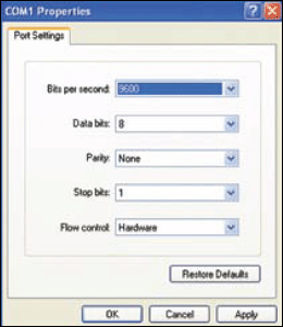
Now select the baud rate as ‘9600,’ data bits as ‘8,’ parity as ‘none,’ stop bits as ‘1’ and flow control as ‘none,’ and click ‘ok’ (refer Fig.7).
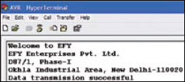
When you press switches S1 through S8, the microcontroller sends the stored message and you will see the message appear on the screen as shown in Fig.8.
Software
The software for this project is given at the end of this article. It is written in ‘C’ language and compiled using Keil μ Vision3 compiler. The finally obtained ‘.hex’ file is downloaded to the microcontroller using a suitable programmer. The source program is well commented and easy to understand.
In the software, first enable timer and serial interrupts. Then configure the timer by mode and reload value to give the correct speed (9600 bits per second). Next, make the transmit interrupt 1 (TI) move the data to SCON. SCON will give the necessary UART signal and your data will be sent serially.
EFY note. The source code of this article is included in the link give below:
Download source code: click here
