


 Presented here is a microcontroller-based special-purpose programmable interval timer for live shows and competitions to record time while the contestants are performing. The main objective of this project is to design an accurate programmable interval timer that can be utilised in inter-college/inter-zonal/inter-university shows and competitions.
In live competitions and shows, each item has a predetermined fixed minimum time, maximum time and grace time. The item being presented should complete between minimum and maximum time. Sometimes, grace time for a few seconds over and above the maximum time is allowed. If it is not completed within the stipulated timeframe, the item presented by that particular team is disqualified.
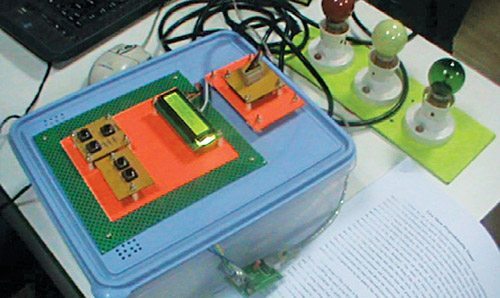
 One may use a stopwatch to monitor the competition but there are chances of inaccuracy or introduction of errors while switching on the stopwatch in the beginning or switching off at the end of a particular item. The audience or the participants can object or raise a complaint for inaccuracy in time allotment. This project comes handy to overcome these problems. It is fully automatic and programmable. It has the flexibility to program the minimum, maximum and grace time period in the database as explained in the software section. The author’s prototype is shown in Fig. 1.
This project has two parts, namely, hardware and software.
Circuit and working
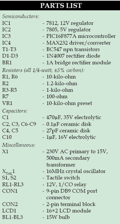
The circuit diagram of programmable interval timer is shown in Fig. 2. It comprises PIC16F877A microcontroller (IC3), MAX232 converter/driver (IC4), three BC547 transistors (T1, T2 and T3), 16×2 LCD (LCD1), 230V AC primary to 15V, 500mA secondary transformer (X1), bridge rectifier module (BR1), regulator ICs 7812 (IC1) and 7805 (IC2) and some other components.
PIC16F877A
This microcontroller is the heart of the hardware section. It has an 8-bit processor with 8k (14-bit words) Flash program memory, 368 bytes data memory and 256 bytes EEPROM. In addition to this, it has three timers, namely, Timer0, Timer1 and Timer2. By using an 8-bit Timer2 having a period register (PR2) and post-scalar ratio as 1:10, interrupt frequency of 100Hz was generated.
For every interrupt, the value of timer variable is increased by one. One-second time elapses when the value of variable reaches 100. The value of one second is the base of the project. When this one second reaches 60, one minute is generated.
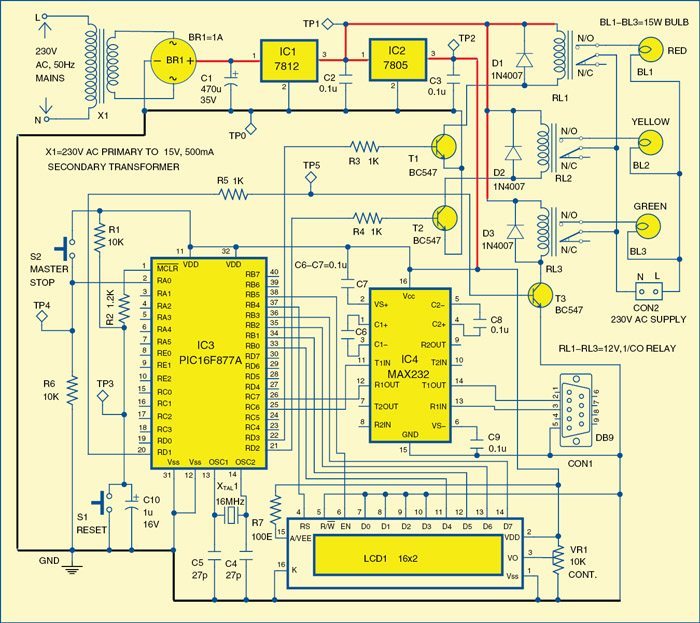
 Port B of the microcontroller is interfaced with 16×2 LCD module to display the values of minutes and seconds. Data pins D4 through D7 of the LCD are connected to RB0 through RB3 pins of the microcontroller, respectively. Port pins RB4 and RB5 of the microcontroller are connected to the register select (RS) and enable (EN) pins of the LCD, respectively. R/W is grounded to keep the write mode always enabled.
Port pins RC6 and RC7 of the microcontroller are configured as a universal synchronous asynchronous receiver transmitter (USART) by connecting to pins 11 and 12 of MAX 232 IC, respectively. Pins 14 and 13 of MAX232 are connected to pins 2 and 3 of COM port DB9 connector, respectively for the data communication with personal computer (PC). You can also use a USB-to-serial converter to connect with the PC in case you do not have a 9-pin COM port on your PC.
Green, yellow and red bulbs (15W each) are connected to RD1, RD2 and RD3 pins of the microcontroller, respectively through three relays. When a team starts presenting an item, green bulb glows. When minimum time is over, green bulb goes off and yellow bulb goes on to indicate that maximum time count started.
As soon as the maximum time is over, yellow bulb starts flickering to indicate that the grace period has started.
When the grace period is over, yellow bulb goes off and the red bulb glows; and immediately the in-built speaker of the PC produces an alert sound, indicating the grace period is over. If the item does not stop before the red bulb glows, the item being presented gets disqualified.
For the next team or contestant, you have to press reset button S1 to repeat the process.
Power supply
The power supply section comprises a 230V AC primary to 15V, 500mA secondary transformer (X1), bridge rectifier module (BR1), regulator ICs 7812 and 7805. The output of bridge rectifier is filtered by capacitor C1 and fed to input of 12V regulator IC1. The 12V drives the three relays RL1 through RL3 and is also fed to input of 5V regulator IC2. The 5V supply drives the microcontroller (IC3), LCD1 and MAX232 (IC4). Resistors R1 and R2 and capacitor C10 form power-on reset circuitry of PIC16F877A microcontroller.
Software
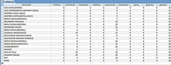
The software part includes two programs, that is, user-interface program and firmware for the microcontroller. Along with these programs, there is an MS Access database file (.mdb) where the user has already entered the minimum, maximum and grace timings (refer Fig. 3). User can change these timings as per requirement, as explained in the next section.


User-interface program
It is written in Visual Basic (VB) 6.0. The purpose of using this program is to connect to the database, to connect the microcontroller and to give audio-visual indication to the user who is monitoring the show.
The VB program has three main forms with different text box command buttons as explained below. The first form is designed such that the VB program first accesses the database records.
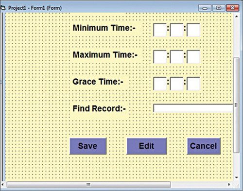
When this program is run, the multiple document interface (MDI) form is displayed with three menu buttons, namely, Entry, Show and Exit. The MDI Form1 program output screenshot is shown in Fig. 4. When the Entry button is pressed, Form1 is opened which allows you to edit the entries in MS Access database file (refer Fig. 5). You can save this information in the database and access it later on.
If Show button is pressed followed by Show Record button, Form2 is opened with four menu buttons, namely, Select COM port, Connect Device, Exit and Next (refer Fig. 6). As shown in Form2, user needs to select the item and then connect to the microcontroller through serial COM port of the PC.
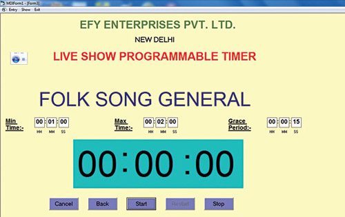
Clicking Next button in Form2 will open up Form3 window. Form3 is the final form of the program where the user should be able to see the name of the item, the minimum, maximum and grace timings along with a green box timer/counter (refer Fig. 7).
The minimum, maximum and grace timings are displayed on the user’s PC screen that is being used to monitor the show. These timings are sent to the microcontroller through RS232 communication interface. The communication between PC and microcontroller is established using MSCOMM control in VB.
The firmware in the microcontroller processes the information and activates the relay driver and turns on the corresponding bulb. Green bulb glows during minimum time, yellow bulb glows during maximum time and red bulb glows after the grace time period is over.
Firmware
The program for microcontroller was written in Basic and compiled using Proton IDE v2.0. The hex code generated by Proton IDE is used to burn into the PIC16F877A using PICSTART Plus programmer.
Construction and testing
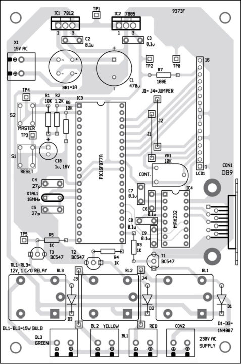
A single-side PCB layout of the circuit is shown in Fig. 8 and its component layout in Fig. 9. All the components are easily available in electronics components shops. After assembling the components on the PCB, you can connect the LCD and three bulbs. Ensure that power supply connections are properly checked.
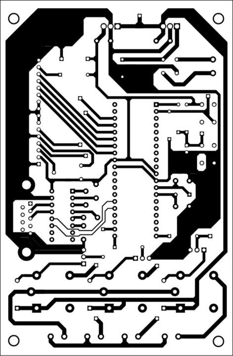
Download the PCB & Component Layout PDFs: Click Here
Download Source Code: Click Here
First connect the circuit to the PC through a DB9 connector or a USB-to-serial converter. Install VB 6.0 in your system. Open the VB project, compile and run the program. Follow the detail as explained in the user-interface program section. Select the exact COM port from the drop-down menu near the Select COMPORT box. To know which COM port you are using, you can view it from the Device Manager of your PC. Note that you need to install an appropriate driver for USB-to-serial converter.
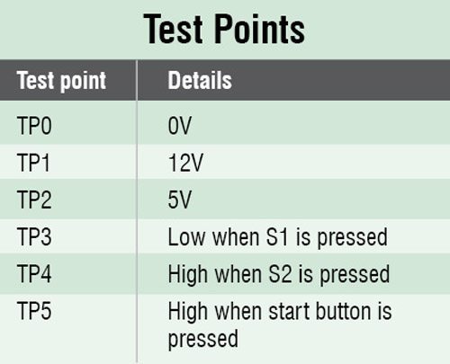
Now, if you press the Connect Device button in Form2, a string is sent to microcontroller device through COM port. This string is received by the microcontroller through MAX 232 IC from COM port. The message PC CONNECTED is displayed on the LCD module (refer Fig. 10). If this message is not received in the LCD, reboot your system and try it again. Vary VR1 to change the contrast of the LCD. Also check voltage levels at various points in the circuit as listed in the test points table.

Once the PC is connected to the microcontroller, name of the item (for example, Folk song general) going to be presented on the stage is selected from the drop-down menu in Form2. After pressing the Next button of the Form2, the item detail along with corresponding minimum, maximum and grace time fetched from MS Access file is displayed on your PC’s screen. The timer will be displayed in the green box in the middle of Form3 as shown in Fig. 7.
This data is also communicated to the LCD module through microcontroller, which also displays the same timing. As soon as a team starts its presentation on the stage, Start button is pressed, the green bulb glows and running time in the green box in Form3 and LCD module keeps on changing simultaneously. When the running time is equal to minimum time of that particular item, the background colour of the green box timer changes from green to yellow and green bulb goes off and yellow bulb glows.
Again, when the timer value is more than the maximum time, this yellow bulb starts blinking (goes on and off for every two seconds), indicating that the grace period has started. Blinking continues till the grace period is over. After expiry of the grace period, yellow bulb goes off and red bulb glows. Then the buzzer of the system (PC/laptop) produces a continuous beep sound, unless you press the Stop button in Form3. This buzzer gives an indication that the item presented has been disqualified.
The above process is repeated for the next team of the same item by pressing S1 reset button on the microcontroller. However, if item is changed then you need to press reset switch S1 and then master stop switch S2.
Dr D.K. Kaushik is principal and Ashok Sharma is technical assistant at Manohar Memorial (P.G.) College, Fatehabad (Haryana)