


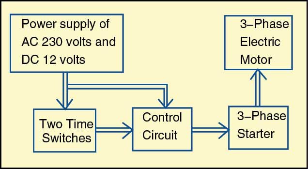
A 3 phase motor programmable controller that automatically turns on/off controller can be made with a programmable time switch. In this case, a maximum of eight-time duration can be programmed. The system has two programmable time switches for setting the starting and stopping times of the motor and two control circuits, which are interfaced with the start and stop switches of the 3-phase motor’s starter. Block diagram of the system is shown in Fig. 1.
Suppose, same clock times are set in both the time switches. So, if the start time of, say, 8 AM is programmed for timer1 ON mode, then 8.01 AM will be programmed for timer1 OFF mode in start time switch. And, if stop time of, say, 9 AM is programmed for timer2 ON mode, then 9.01 AM will be programmed for timer2 OFF mode in stop time switch.
When the time reaches 8 AM, the start time switch connects the primary of transformer X1 to 230V AC. The output of the power supply gets connected to reset pin 4 of IC1. R4 and C3 act as self-triggering components. The output of the monostable at pin 3 becomes high for a period equal to 1.1×R5×C4, which is nearly equal to five seconds.

3 phase motor programmable controller circuit
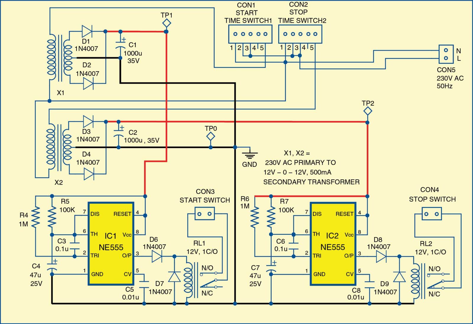
As pin 3 of IC1 is high, relay RL1 gets energised for five seconds, which, in turn, shorts the start switch, extending the 3-phase supply to the motor. This is virtually similar to physically press the start switch of the 3-phase motor starter for five seconds.
When the time reaches 9 AM, the second time switch (stop switch) provides 230V AC to the primary of transformer X2. Again, by using a full-wave rectifier and filter circuit, 12V DC is provided to the second monostable circuit having relay RL2.
Normally-closed (N/C) terminal of the relay is connected in series with the stop switch of the starter of the 3-phase motor. So, the relay breaks the circuit to stop the motor.
This is an example of one time duration of 8am to 9am. In this way, a maximum of eight time durations can be programmed to switch the 3-phase electric motor on and off.
There is provision for setting days of the week for the controller to function. For instance, it can be set to work from Monday to Friday, Monday to Saturday, all seven days of the week, or only on a particular day of the week.
This system can find many applications, including switching on a water pump in a multi-storeyed commercial building to fill overhead tanks only for five or six days in a week. It can also prove useful for farmers, industrial units or railway stations where 3-phase motors are used.
Circuit operation
Two identical power supply circuits are built around transformers X1 and X2 with associated components as shown in Fig. 2. The arrangement provides 12V DC to two control circuits built around two 555 timers IC1 and IC2, which are configured in monostable mode.
The two time switches used in this system are Frontier-made, model TM-619-2. These operate on 230V AC at 50Hz. Each switch has a built-in single changeover relay with contact rating of 16A. It has an LCD display with buttons such as CLOCK, TIMER, DAY, HOUR, MIN and MANUAL, as shown in Fig. 3. By using these buttons, a real-time clock is set and various time durations are programmed.
The time switch is a programmable digital device that has a digital real-time clock and can program for a maximum eight time durations. The time durations can be for a particular day, alternate days, Monday to Friday, Monday to Saturday, or Monday to Sunday.
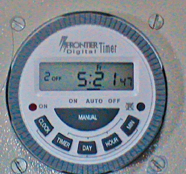
By holding clock button, real time is set by using HOUR, MIN and DAY buttons, while various time durations are programmed by using TIMER, HOUR, MIN and DAY buttons.
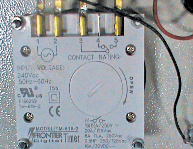
There are three modes, namely, ON, AUTO and OFF, written just below the display. After programming time durations, a black horizontal line segment is kept over AUTO mode from OFF mode by pressina g MANUAL button. The time switch provides five external pins numbered 1 to 5 as shown in Fig. 4.
230V AC is applied across pins 1 and 2 of connectors CON1 and CON2 for start and stop switches, with pin 1 being neutral. Live pins 2 are joined by wire to pins 3 and output voltage is taken from pins 1 and 5. There is a provision of button cell CR2032 to hold the clock and programmed times. That means, even if 230V AC is turned off, the clock and programmed times are not disturbed (during mains failure) for 60 to 90 days. When mains power is present, the cell is charged continuously.
The control circuit has two monostable multivibrators for the time delay of five seconds. The start time switch1 is connected to the first monostable multivibrator built around IC1 as shown in Fig. 2.
The real-time clock of time switch1 is set by pressing and holding CLOCK button and adjusting the time by using HOUR, MIN and DAY buttons. If first time duration of 8am to 9 AM has to be programmed at weekly mode, then 8am is programmed at 1 ON mode and 8.01 AM is programmed at 1 OFF mode in the first time switch by selecting weekly mode.
The motor is switched off by using the second multivibrator circuit as shown in Fig. 2, in which N/C and common terminals of relay RL2 are connected in series with off switch of the starter.
Real-time clock is set by pressing and holding CLOCK button and adjusting the time by using HOUR, MIN and DAY buttons. Off time, that is, 9am, is programmed at 1 On mode with weekly day selection by pressing the TIMER button.
Again, by pressing TIMER button, 9.01 AM is set at 1 OFF mode with weekly day selection in the second time switch. When time 9 AM is reached, the second time switch provides 230V AC across the primary of step-down transformer X2, and the second full-wave rectifier outputs 12V DC. This voltage goes to the second monostable multivibrator circuit as shown in Fig. 2.
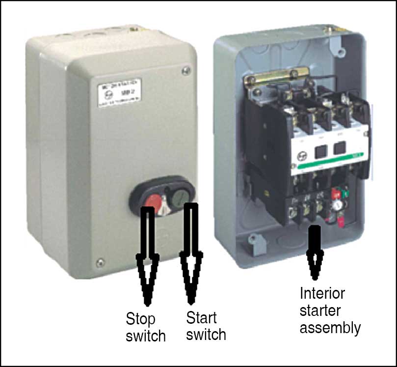
Fig. 5 shows the photograph of a typical starter for a 3-phase electric motor along with the interior assembly of the starter. On the right of the photograph, two push-buttons are shown; the green push-button is used to start the motor and the red push-button is used to stop it. It also has a relay coil. When the start switch is pressed momentarily, current flows through the coil, relay strip is pulled towards the iron of the coil and 3-phase voltage gets applied to the motor.
Download PCB and component layout PDFs: click here
Construction and testing
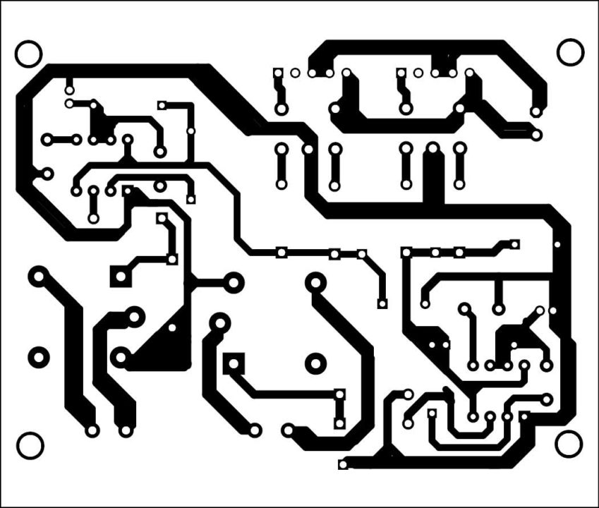
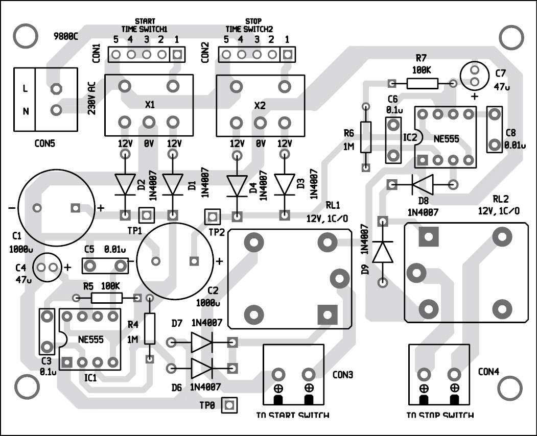
An actual-size, single-side PCB of the 3 Phase Motor Programmable Controller is shown in Fig. 6 and its component layout in Fig. 7.
EFY note. Reset the time switch if there is any difficulty in setting time on the time switch.
Dr R.V. Dhekale is currently working as associate professor and head of department (Physics) at Kisan Veer Mahavidhyalaya, Maharashtra. He is a life member of Indian Association of Physics Teachers.
This project was first published on 16 June 2017 and was recently updated on 18 January 2019.
hello,
Is this project capable to use with home cooler motor pump because it runs regularly and consume lots of water so
is just wanted to know is we use to run motor periodically to reduce to consumption of water.
Please my name is Muubana perpetual,I’m a student in engineering. Pls my project topic is design and construction of automatic start and stop switch used in an industrial Air compressor. I need the write up on this project topic, pls something should help me
what are the advantages and disadvantages of this project.
plz let us know.