


 This simple, economical and versatile water level controller circuit switches on the motor pump when water in the overhead tank falls below the lowest level and turns it ‘off’ when the tank is full. Moreover, if the pump is running dry due to low voltage, it sounds an alarm to alert you to switch off the water level controller circuit (and hence the motor pump) to avoid coil burn and power wastage.
The water level controller circuit is built around IC 555 (IC2) to monitor the water level in the overhead tank and ‘on’/‘off’ status of the motor through the inverter and driver circuits. The transistor switch circuitry monitors the flow of water and raises an alarm if the pump runs dry.
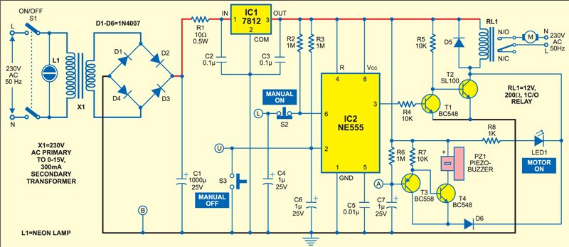
Water level controller circuit
Power supply is obtained through step-down transformer X1, diodes D1 through D4, capacitor C1, series current-limiting resistor R1, regulator IC1, and noise-filtering capacitors C2 and C3. The set-up for the water-level sensing electrodes is shown in Fig. 2. Electrodes are suspended into the tank such that they don’t touch each other. Points B, L and U of the water level controller circuit are connected to the respective points of the sensor electrodes assembly.

Circuit Operation
When water in the tank is below the lowest level L1, all the electrodes are electrically separated and hence points L and U (pins 6 and 2 of IC2, respectively) are pulled up to the supply voltage through resistors R2 and R3, respectively. Therefore, to reset IC2 the output of IC2 at pin 3 goes low. As a result, transistor T1 stops conducting to drive transistor T2 and relay RL1 energises. The motor pump now starts running to fill the tank with water. Freewheeling diode D5 prevents chattering of the relay due to the back emf produced by the relay coil.
When the water level rises to bridge the electrodes, because of the conductivity of water, pin 6 (E1) is pulled down to ground (E2). This does not alter the output state of IC2, which maintains its previous state, and the motor keeps running. When water rises to the overflow level L2 and touches electrode E3, point U (pin 2 of IC2) is connected to already sunken ground electrode E2, thereby triggering it. IC2 resets to give a high output at pin 3. This is inverted by transistor T1 to cut off transistor T2 and de-energise relay RL1. The motor pump now stops to prevent water overflow.

Water level falling below level
As water is consumed, the water level comes down leaving electrode E3 isolated from ground electrode E2. Now point U (pin 2 of IC2) is pulled up to the supply voltage. This does not change the output state of IC2 and the motor remains switched off.
When water level again falls below electrode E2, IC2 resets to cut off transistor T1. Transistor T2 conducts to energise relay RL1 and the motor is powered to run. This is how the process continues. LED1 glows whenever the relay energises, indicating that the motor pump is running.
As the values of resistors R2 and R3 are very high, corrosion of electrodes is very little. Capacitors C2 through C7 filter out unwanted noise. Switches S2 and S3 can be used to manually switch on and off the motor pump, respectively, when water is in between the upper and lower levels. Switch S1 is used to disable the unit during dry pump run or while flushing the tank.
Water level controller: In-tank setup
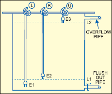
For the sensor electrodes, use a moulded-type AC chord (used for tape recorders) with its pair of wires sleeved at the end and connected together to form the electrode. Other electrodes can be made similarly. These three AC chords are suspended inside the tank from a longitudinally cut PVC pipe (used for electrical wiring).
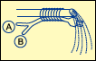
The arrangement for the dry pump sensor is shown in Fig. 3. A moulded-type AC chord with its pair of wires sleeved at the end can be attached firmly to the delivery pipe such that water falls onto the plug leads. The sleeved ends are connected to points A and B of the water-level controller circuit.
Alarm circuit
The circuit for dry-run alarm comprises transistors T3 and T4, piezobuzzer PZ1, resistors R6 and R7, and capacitor C7. When points A and B of the dry-running sensor (see Fig. 3) are bridged by water being delivered by the pipe, transistor T3 conducts to drive transistor T4 into cut-off state and therefore the DC buzzer remains silent.
When the pump runs dry, points A and B are electrically apart causing transistor T3 to cut off because of pull-up resistor R6. Transistor T4 conducts due to the emitter drop of transistor T3, which activates the DC buzzer to sound an alarm indicating dry running of the pump.
The alarm circuit is enabled only when transistor T2 conducts, i.e., only when the motor pump runs. Diode D6 isolates the relay driver circuitry to prevent transistor T3 from extending ground to the relay through transistor T3 and water being delivered. As soon as the pump is switched on, the alarm sounds until water reaches the delivery port.
House the controller circuit (including the power supply) in a cabinet. Use a four-core shielded cable for wiring the tank electrodes to the controller unit fixed near the motor switch.
Testing the water controller
To test the circuit, proceed as follows:
1. Switch on power to the circuit.
2. LED1 glows and relay RL1 energises to produce an alarm from piezobuzzer PZ1, indicating that none of the circuit points A, B, U and L is shorted through water (i.e., water in the tank is below the lowest limit). The energised relay indicates ‘on’ status of the motor.
3. Immerse points A and B in water. The buzzer stops sounding to indicate that water is flowing out of the pipe to short points A and B. This confirms no dry run.
4. Immerse points B and L in water, as would be the case when the water level rises. Momentarily touch point U to water. LED1 goes off and the relay de-energises to turn the pump ‘off.’ This would be the case when water touches the overflow limit.
5. Remove points A and B from water assuming that the flowing water that was shorting points A and B has stopped. Now, although water is not flowing, the buzzer does not sound as the relay is already de-energised.
6. Remove points U and B from water, assuming that water has fallen below the lowest limit because of consumption. Two seconds later, LED1 glows and the relay energises.
Precautions
1. Make sure that water being delivered from the water pipe doesn’t touch any of the suspended water-level sensors.
2. Mount the alarm sensor firmly onto the water pipe such that electrodes A and B are shorted by water flowing out of the pipe.
3. Use a properly shielded cable to carry signals from the tank to the water-level controller unit.
More projects available here.

Sir,
Please let me know if pcb and the kit is available for this versatile water level controller is available at Bombay.
If yes, where and the cost.
If no what to do?
Sorry, PCB and complete kit of this circuit is not available with us. However, you can get complete kits of water level controller from our associates M/s Kits ‘n’Sapres. Please visit them at https://www.kitsnspares.com/user1/buyproduct.asp
I want to design a micro controller based customized water level controller,
please tell me how does it cost if i program a micro controller from a programmer.
Helo sir,
how to contacted to motor stater sir
Kindly elaborate your query.
Hi, thank for your time and the post. Shall I know where to connect dry run contact point. If possible please email me [email protected].
With Best Regards.
whenever there is a power fluctuation, the circuit board of our water level controller gets burnt and it doesnt work automatically. However, the manual operation works fine. This is the 2nd time it happens. Both the times, the service provider has repaired and replaced it. He says there must be some problem with the power supply. Is it true? The funny part is the fuse doesn’t blow at all. What could be the probable reason for it.