


 Using this light operated door latch circuit, you can close or open the door of your room remotely from your bed. You just have to focus the torchlight on the light dependent resistor (LDR) of the circuit, which you can install inside your room at a suitable position.
Light operated door latch circuit
The circuit comprises a control unit and a driver unit for the stepper motor circuit used to latch/open the door.
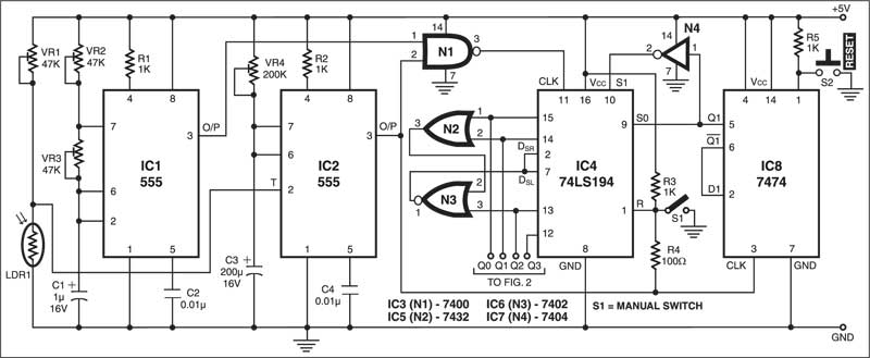
The control unit comprises two timer 555 ICs (IC1 and IC2), NAND gate IC (IC3), 4-bit bidirectional universal shift register (IC4), OR gate (IC5), NOR gate (IC6), hex inverter (IC7) and dual D-type positive-edge triggered flip-flop (IC8) as shown in Fig. 1. The driver circuit shown in Fig. 2 uses four Darlington pair transistors (T1 through T8) to increase the current carrying capability for operating the stepper motor.

The astable multivibrator built around timer 555 (IC1) has a time period of 1.5 seconds. The monostable built around IC2 is triggered when torchlight is focused on light-dependent resistor LDR1. Sensitivity potentiometer VR1 is adjusted to ambient light. Normally, the LDR is kept covered to avoid its activation by ambient light.
Circuit operation
When torchlight is focused on the LDR, the monostable (IC2) is triggered. The ‘on’ time of IC2 is adjusted to 15 seconds by potentiometer VR4. The outputs at pin 3 of astable IC1 and monostable IC2 are fed to NAND gate N1 of IC3. The Q0 and Q1 outputs of shift register IC4 are ORed by OR gate N2 and its output is fed to NOR gate N3. The Q2 output of IC4 forms the second input for NOR gate N3. The output of NOR gate N3 goes to shift-right and shift-left serial data inputs (pins 2 and 7) of IC4.

Mode-control inputs S0 and S1 are used for direction changing of shift register IC4. The Q1 output of dual D-type flip-flop IC8 is fed to S0 directly and to S1 after inversion by N4.
The output of monostable IC2 resets IC4 via resistor R4, which stops the stepper motor. You can also manually stop the stepper motor by pushing switch S1 to ‘on’ position.
Switch S2 is used for resetting dual D-type flip-flop IC8. The monostable output also provides clock to the D flip-flop operating in toggle mode by connecting Q1 to D1 of IC8.
Fig. 2 shows the driver unit for the stepper motor, along with windings details of the stepper motor. Connect Q0 through Q3 outputs of IC4 in the control unit (Fig. 1) to positive and ground power supply terminals of the driver unit (Fig. 2). The waveform drive pattern of shift outputs of IC4 is shown in the table.
When you direct torchlight on the LDR, the stepper motor runs in one direction to latch the door. If you again focus torchlight on the LDR, the stepper motor runs in reverse direction to open the latch.
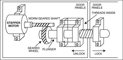
Fig. 3 shows the locking arrangement operated by the stepper motor.
Note
During testing at EFY lab, a stepper motor for read/write head positioning in a 1.2 MB floppy disk drive unit, operating off 12V with 3.6-degree revolution per step, was used. Connect the coloured terminal wires of the motor to the driver unit as shown in Fig. 2.
This article is a part of the Top 10 LDR-based Electronics Projects. If you want to read more projects based on LDRs can go through this article.
The article was first published in July 2004 and has recently been updated.